Table of Contents
Advertisement
Quick Links
N1100HC CONTROLLER
HEAT/COOL PROCESS CONTROLLER
1
MAIN FEATURES
•
Universal multi-sensor input without hardware change.
•
Sensor break protection in any condition.
•
Control outputs: relay, linear 4-20 mA, 0-20 mA, pulsed output
•
2° control output for refrigeration, with independent proportional
band and cycle time.
•
Overlap adjustment for the control outputs.
•
Up to 4 alarms. Up to 2 timer relay alarms.
•
Process Variable or Setpoint 4-20 mA or 0-20 mA analog
retransmission.
•
Auto/Manual "bumpless" transfer.
•
Up to 3 digital inputs with 5 programmable functions.
•
Programmable Soft Start (0 to 9999 seconds).
•
RS-485 digital communication; RTU MODBUS protocol.
•
Unique electronic 8-digit serial number can be viewed at the
display.
•
Firmware version displayed during power up.
•
Keyboard password protection.
2
SPECIFICATIONS
•
Dimensions: 48 x 48 x 110 mm (1/16 DIN).
•
Approximate weight: 150 g
•
Panel cut-out: 45,5 x 45,5 mm (+0.5 -0.0 mm)
•
Terminal connection: 18 screws accepting 6.3 mm fork lugs.
•
Power: 100 to 240 Vac/dc, 50/60 Hz. Max. Consumption: 3 VA
•
Operating environment: 0 to 55 °C, Relative humidity
(maximum): 80 % up to 30 ºC. For temperatures above 30 ºC,
decrease 3 % per ºC.
INPUT
•
Keyboard selection of input type (refer to Table 1)
•
Internal resolution: 19500 levels
•
Display resolution: 12000 levels (from -1999 to 9999)
•
Input sample rate: 5 per second
•
Thermocouples J, K and T: 0.25 % of span ±1 ºC
Accuracy:
Thermocouple S: 0.25 % of span ±3 ºC
Pt100: 0.2 % of span
4-20 mA, 0-50 mV, 0-5 Vdc: 0.2 % of span.
•
Input impedance: 0-50 mV, Pt100 and thermocouples: >10 MΩ
0-5 V: >1 MΩ
4-20 mA: 100 Ω
•
Pt100 measurement: DIN 43760 standard (α=0.00385).
Excitation current: 170 µA. 3-wire circuit, cable resistance
compensation.
•
Analog output: 0-20 mA or 4-20 mA, 1500 levels, 550 Ω max.
NOVUS AUTOMATION
V2.0x A
-
CONTROL OUTPUT (Standard Version (up to 3 outputs):
•
Two 3 A / 250 Vac Relays (3 A / 30 Vdc);
•
Isolated 0-20 mA or 4-20 mA control output or PV or SP
retransmission, 1500 level resolution, 550 Ω max. Load;
•
Logic pulse for SSR drive: 0 or 20 mA;
•
Any of the above and options 1 and 2 can be selected as the
main control output and the remaining outputs can be set as
alarms;
•
Programmable PWM cycle from 0.5 sec. and 100 sec.;
•
Start up 3 seconds after power up;
With Option Modules (up to 5 outputs)
•
Option 1: 3 A / 250 Vac (3 A / 30 Vdc) SPDT Relay (3rd relay);
•
Option 2: two digital I/Os (input: dry contact; output 5 Vdc, 10 mA
max.). Option 3: heater break detection;
•
Option 4: RS-485, MODBUS RTU protocol, 1200 to 19200 bps;
ALARMS
•
Up to 4 alarms can be set with 9 different functions for each one.
Other alarm features are:
•
2 Timing alarms, programmable from 0 to 6500 sec., with
advanced functions, ideal for servo-positioning
•
Independent power-up inhibition of the 4 alarms
•
Programmable hysteresis for the 4 alarms
3
OPERATION
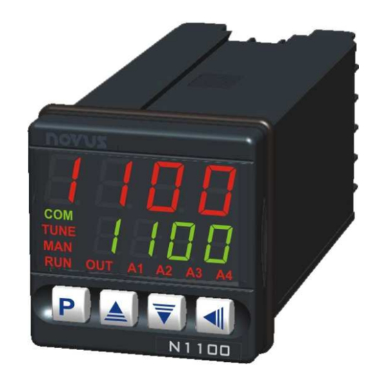
The front panel is shown in Figure 1.
messages
Status display/PV: shows the value of PV (Process Variable). When
in programming mode, shows the parameter name.
Parameter display/SV: shows the SV (Setpoint Variable) value and
the value of other parameters of the controller.
COM Indicator: Flashes when communication messages are sent by
the controller.
TUNE Indicator: Lights during the execution of PID automatic
tunning.
MAN Indicator: Lights when the controller is in manual.
RUN Indicator: Lights when the controller is active, with control and
alarm outputs enabled.
OUT Indicator: For relay or pulse control output, reflects the actual
state of the output. If an analog output is assigned for control, lights
continuously.
Keys
Figure 1 - Front panel parts
Status Display
PV
Parameter Display
SP
1/7
Advertisement
Table of Contents

Related Manuals for Novus N1100HC


Summary of Contents for Novus N1100HC
- Page 1 N1100HC CONTROLLER HEAT/COOL PROCESS CONTROLLER V2.0x A CONTROL OUTPUT (Standard Version (up to 3 outputs): MAIN FEATURES • Two 3 A / 250 Vac Relays (3 A / 30 Vdc); • Universal multi-sensor input without hardware change. • Isolated 0-20 mA or 4-20 mA control output or PV or SP •...
-
Page 2: Program Security
N1100HC Controller A1, A2, A3 and A4 Indicators: Status of the alarms. TYPE CODE CHARACTERISTICS range: -50 to 760 °C (-58 to 1400 ºF) 0 0 0 0 - PROG key: used to walk through the menu cycles range: -90 to 1370 °C (-130 to 2498 ºF) - Page 3 N1100HC Controller CODE I/O Type I/O Function TYPE PROMPT ACTION Digital Output Digital Output to be set by the serial comm. 0 0 0 0 Disabled No active alarm. This output can be Digital Output Alarm 1 Output 1 1 1 1...
-
Page 4: Installation
N1100HC Controller 5.7 SOFT-START CONFIGURATION PARAMETERS Defines the time interval for the output to reach its maximum value 7.1 OPERATION CYCLE SfSt” (100 %). The soft-start value is programmed in the “SfSt SfSt SfSt parameter. PV Indication PV AND SV INDICATION: The status display shows... -
Page 5: Alarm Cycle
N1100HC Controller 7.3 CONTROL # 2 PARAMETERS xya1 xya1 xya1 xya1 ALARM 1 HYSTERESIS: Defines the differential range between the PV value at which the alarm is PROPORTIONAL BAND: Percentage of maximum turned on and the value at which it is turned off (in input span. -
Page 6: Calibration Cycle
N1100HC Controller 7.7 I/O CYCLE (INPUTS AND OUTPUTS) CONTROL # 2 The N1100HC incorporates a second control output with proportional I/O 1 FUNCTION: Selects the I/O function to be used action. This second control output is intended primarily for at I/O 1 (relay 1). Options 0 to 5 are possible for this refrigeration, since the control #1 is normally used for heating. -
Page 7: Serial Communication
N1100HC Controller The program tolerance “ defines the maximum deviation Ptol” Ptol 10 AUTO TUNE Ptol Ptol between PV and SV for the execution of the profile. If this deviation is During auto tune the process is controlled in ON/OFF mode at the...
Need help?
Do you have a question about the N1100HC and is the answer not in the manual?
Questions and answers