Table of Contents
Advertisement
Quick Links
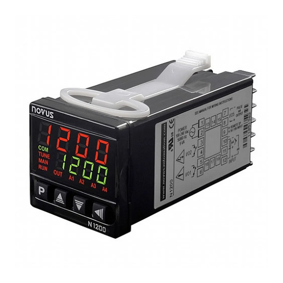
N1200HC Controller
PROCESS CONTROLLER – INSTRUCTIONS MANUAL – V2.0x C
SAFETY ALERTS
The symbols below are used on the equipment and throughout this
document to draw the user's attention to important operational and
safety information.
CAUTION:
Read the manual thoroughly
before installing and operating the
equipment.
All safety related instructions that appear in the manual must be
observed to ensure personal safety and to prevent damage to either
the instrument or the system. If the instrument is used in a manner not
specified by the manufacturer, the protection provided by the
equipment may be impaired.
INTRODUCTION
The N1200HC is an extraordinarily versatile process controller. It
accepts in a single model virtually all the sensors and signals used in
the industry and provides the main output types required for the
operation of diverse processes.
The configuration can be performed directly on the controller or through
the USB interface. The NConfig software (free) is the configuration
management tool. Connected to the USB of a Windows computer, the
controller is recognized as a serial communications port (COM) running
with a Modbus RTU protocol.
Through the USB interface, even if disconnected from the power
supply, the configuration performed in a piece of equipment can be can
be saved in a file and repeated in other pieces of equipment that
require the same configuration.
It is important that the users read carefully this manual before using the
controller. Verify if the release of this manual matches the instrument
version (the firmware version is shown when the controller is
energized). The N1200HC main characteristics are:
• Multi-sensor universal input, with no hardware change;
• Protection for open sensor in any condition;
• Two separate control outputs: heating and cooling;
• Self-tuning of PID parameters;
• Automatic / Manual function with "bumpless" transfer;
• Three alarm outputs in the basic version, with functions of
minimum, maximum, differential (deviation), open sensor and
event;
• Timer functions that can be associated to the alarms;
• Retransmission of PV or SP in 0-20 mA or 4-20 mA;
• Input for remote setpoint;
• Digital input with 5 functions;
• Programmable soft-start;
• 20 setpoint profile programs with 9 segments each, with the ability
to be linked together for a total of 180 segments;
• Password for parameters protection;
• Universal power supply.
NOVUS AUTOMATION
CAUTION OR DANGER:
Electrical Shock Hazard
CONFIGURATION / FEATURES
INPUT TYPE SELECTION
The type of input to be used by the controller is defined in the device
configuration. Table 1 shows all available options.
TYPE
CODE
J
Range: -110 to 950 ºC (-166 to 1742 ºF)
Tc j
K
Range: -150 to 1370 ºC (-238 to 2498 ºF)
Tc k
T
Range: -160 to 400 ºC (-256 to 752 ºF)
Tc t
N
Range: -270 to 1300 ºC (-454 to 2372 ºF)
Tc n
R
Range: -50 to 1760 ºC (-58 to 3200 ºF)
Tc r
S
Range: -50 to 1760 ºC (-58 to 3200 ºF)
Tc s
B
Range: 400 to 1800 ºC (752 to 3272 ºF)
Tc b
E
Range:-90 to 730 ºC (-130 to 1346 ºF)
Tc e
Pt100
Range: -200 to 850 ºC (-328 to 1562 ºF)
Pt
0-20 mA
L0. 2 0
4-20 mA
L4. 2 0
0–50 mV
L0. 5 0
Programmable indication from -1999 to 9999.
0-5 Vdc
L0. 5
0-10 Vdc
L0. 1 0
ln j
Ln k
ln t
ln n
4-20 mA
NON
ln r
Indication range depends on the selected sensor.
LINEAR
ln s
ln b
ln E
Ln. P t
Table 1 - Input types
Note: All input types are factory calibrated.
CONFIGURATION OF OUTPUTS, ALARMS AND DIGITAL INPUTS
The controller input and output channels (I/O) can assume multiple
functions: control output 1 or 2, digital input, digital output, alarm
output, retransmission of PV and SP. These channels are identified
as I/O 1, I/O 2, I/O 3, I/O 4 and I/O 5.
The basic controller model comes loaded with the following features:
I/O 1-
output to Relay SPST-NA;
I/O 2-
output to Relay SPST-NA;
I/O 5-
current output, digital output, digital input;
Optionally, other features can be added, as shown under the item
Identification in this manual:
- 3R:
I/O3 with output to SPDT relay;
- DIO: I/O3 and I/O4 as digital input and output channels;
- 485:
Serial Communication;
The function to be used in each channel of I/O is defined by the user
in accordance with the options shown in the Table 2.
RANGE OF MEASUREMENT
Linear Signals
Non Linear Analog Signals
1/12
Advertisement
Table of Contents

Related Manuals for Novus N1200HC


Summary of Contents for Novus N1200HC
- Page 1 Linear Signals 0–50 mV L0. 5 0 Programmable indication from -1999 to 9999. The N1200HC is an extraordinarily versatile process controller. It 0-5 Vdc L0. 5 accepts in a single model virtually all the sensors and signals used in 0-10 Vdc the industry and provides the main output types required for the L0.
-
Page 2: Configuration Of Alarms
N1200HC Controller kprg - Digital Input with Hold Program function • FUNCTION OF I/O CODE TYPE OF I/O Defines channel as Digital Input with the function of commanding the Without Function Output execution of the selected setpoint profile program. Available for I/O5... - Page 3 N1200HC Controller For a negative SPA1 value, the Differential alarm triggers when the INITIAL BLOCKING OF ALARM value of PV is within the range defined above. The initial blocking option inhibits the alarm from being recognized if an alarm condition is present when the controller is first energized.
- Page 4 N1200HC Controller The proportional band 2 (Pb2) and the level time of PWM 2 (Ct2) are SAFE OUTPUT VALUE WITH SENSOR FAILURE independent. Here you must set the minimum and maximum power A function that sets the control output 1 in a safe condition for the for control 2.
-
Page 5: Recommendations For The Installation
N1200HC Controller RECOMMENDATIONS FOR THE INSTALLATION 4-20 mA: • • The wires of the input signals must be disposed separated of the The connections for current signals 4-20 mA must be carried-out power and outputs wirings, if possible, in grounded ducts. - Page 6 N1200HC Controller CONFIGURATION PARAMETERS Display of PV/Programming: Displays the current value of PV (Process Variable). When in configuration mode, it shows the parameters names. OPERATION LEVEL Display of SP/Parameters: Displays the value of SP (Setpoint). PV AND SP INDICATION: The upper display PV Indication When in configuration mode, it shows the parameters values.
-
Page 7: Programs Parameters Level
N1200HC Controller (Proportional band 1) – PROPORTIONAL for Loop break detection time - Time interval of the Lbd. t control output 1: Value of the term P of the control LBD function. Maximum time interval for the mode PID, in percentage of the maximum span of response of PV to commands from the control the input type. -
Page 8: Scale Parameter Level
N1200HC Controller Alarm Time t2 - Defines the temporization time t2 Digital communication Baud Rate selection, in A1t2 bavd for the alarms time functions. In seconds. kbps 1.2, 2.4, 4.8, 9.6, 19.2, 38.4, 57.6 and 115.2 A2t2 The value 0 (zero) disables the function. -
Page 9: Programs Of Ramp And Soak
N1200HC Controller PROGRAMS OF RAMP AND SOAK Hardware Type - Parameter that informs the ktyp controller about the hardware optionals installed. It This feature allows the creation of a behavior profile for the process. should not be altered by the user, except when an... -
Page 10: Maintenance
N1200HC Controller Automatic tuning: In the beginning of the automatic tuning the Whenever the parameter ATUN is altered by the operator into a controller has the same behavior of an ON/OFF controller, applying value different from OFF, an automatic tuning is immediately initiated minimum and maximum performance to the process. -
Page 11: Serial Communication
Registers Table Serial Communication in the N1200HC section of our web site – www.novusautomation.com. Select the screen “ovxC”. Press the keys for the controller to recognize the calibration process of the current All registers are 16 bit signed integers. -
Page 12: Control Output
N1200HC Controller All input and output types are factory-calibrated. Thermocouples according to standard NBR 12771 / 99, RTD’s NBR 13773 / 97; ANALOGICAL OUTPUT (I/O5): ..0-20 mA or 4-20 mA, 550Ω max. 31000 levels, insulated, for control or retransmission of PV and SP CONTROL OUTPUT: 2 Relays SPST-NA (I/O1 and I/O2): 1.5 A / 240 Vac, general use...
Need help?
Do you have a question about the N1200HC and is the answer not in the manual?
Questions and answers