Table of Contents
Advertisement
Quick Links
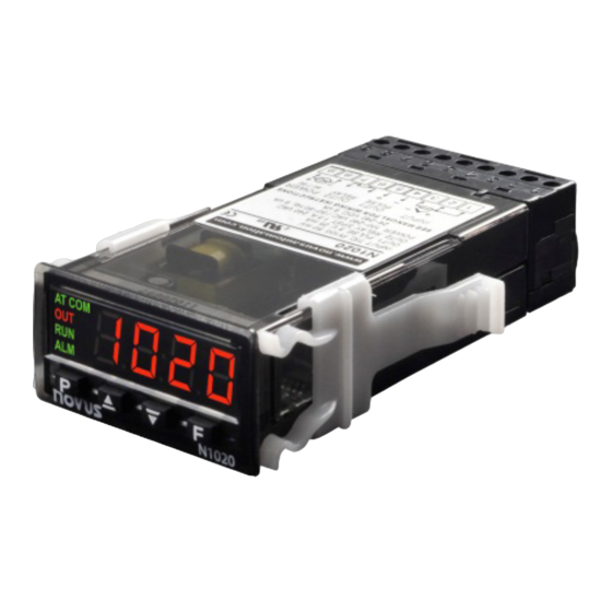
N1020 Temperature Controller
INSTRUCTIONS MANUAL – V1.2x B
INTRODUCTION
N1020 is a small and yet powerful temperature controller. It accepts
most of the temperature sensors used in industry and its 2 outputs can
be configured independently as control or alarm output. It also
embeds an auto-adaptive PID control algorithm for best system
performance.
Configuration can be performed either directly on the controller or via
the USB interface once QuickTune software has been installed on the
computer to be used. Once connected to USB, the device will be
recognized as a serial communication (COM) port operating with
Modbus RTU protocol.
Through the USB interface, even if disconnected from the power supply,
the configuration performed in a piece of equipment can be can be saved
in a file and repeated in other pieces of equipment that require the same
configuration.
It is important that the users read carefully this manual before using
the controller. Verify if the release of this manual matches the
instrument version (the firmware version is shown when the controller
is energized). The N1020 main characteristics are:
LED Display, red, high brightness.
•
Multi-sensor universal input: Thermocouples, Pt100, and 50 Mv.
•
Self-tuning PID parameters.
•
2 outputs: 1 relay and 1 logical pulse for SSR.
•
Output functions: Control, Alarm1, and Alarm 2.
•
8 distinct alarm functions.
•
Programmable timer.
•
Function key for enabling/disabling outputs, resetting the timer or
•
turning the timer ON/OFF.
Programmable Soft Start.
•
Rate function.
•
Password for parameters protection.
•
Capability of restoring factory calibration.
•
USB INTERFACE
The USB interface is used to CONFIGURE, MONITOR, or UPDATE
the controller FIRMWARE. The user should use QuickTune software,
which offers features to create, view, save and open settings from the
device or files on the computer. The tool for saving and opening
configurations in files allows the user to transfer settings between
devices and perform backup copies.
For specific models, QuickTune allows to update the firmware
(internal software) of the controller via the USB interface.
For MONITORING purposes, the user can use any supervisory
software (SCADA) or laboratory software that supports the MODBUS
RTU communication over a serial communication port. When
connected to a computer's USB, the controller is recognized as a
conventional serial port (COM x).
The user must use QuickTune software or consult the DEVICE
MANAGER on the Windows Control Panel to identify the COM port
assigned to the controller.
NOVUS AUTOMATION
The user should consult the mapping of the MODBUS memory in the
controller communication manual and the documentation of the
supervision software to start the MONITORING process.
Follow the procedure below to use the USB communication of the
device:
1. Download QuickTune software from our website and install it on
the computer. The USB drivers necessary for operating the
communication will be installed with the software.
2. Connect the USB cable between the device and the computer. The
controller does not have to be connected to a power supply. The
USB will provide enough power to operate the communication
(other device functions may not operate).
3. Run the QuickTune software, configure the communication and
start the device recognition.
The USB interface IS NOT SEPARATE from the
signal input (PV) or the controller's digital inputs
and outputs. It is intended for temporary use
during
CONFIGURATION
periods.
For the safety of people and equipment, it must
only be used when the piece of equipment is
completely disconnected from the input/output
signals.
Using the USB in any other type of connection is
possible but requires a careful analysis by the
person responsible for installing it.
When MONITORING for long periods of time and
with
connected
recommend using the RS485 interface, which is
available or optional in most of our products.
INSTALLATION / CONNECTIONS
The controller must be fastened on a panel, following the sequence of
steps described below:
Prepare a panel cut-out, according to Specifications.
•
Remove the mounting clamps from the controller.
•
Insert the controller into the panel cut-out.
•
Slide the mounting clamp from the rear to a firm grip at the panel.
•
INSTALLATION RECOMMENDATIONS
To minimize the pick-up of electrical noise, the low voltage DC
•
connections and the sensor input wiring should be routed away
from high-current power conductors. If this is impractical, use
shielded cables. In general, keep cable lengths to a minimum.
All electronic instruments must be powered by a clean mains
•
supply, proper for instrumentation.
It is strongly recommended to apply RC'S FILTERS (noise
•
suppressor) to contactor coils, solenoids, etc.
In any application it is essential to consider what can happen when
•
any part of the system fails. The controller features by themselves
can't assure total protection.
and
MONITORING
inputs
and
outputs,
we
1/9
Advertisement
Table of Contents

Subscribe to Our Youtube Channel
Related Manuals for Novus N1020-A


Summary of Contents for Novus N1020-A
- Page 1 MANAGER on the Windows Control Panel to identify the COM port In any application it is essential to consider what can happen when • assigned to the controller. any part of the system fails. The controller features by themselves can’t assure total protection. NOVUS AUTOMATION...
- Page 2 Available at terminals 4 and 5. OUT2 Relay SPST-NO, 1.5 A / 240 Vac. Available at terminals 6 and 7. Note: The outputs can be configured independently from each other, for example, both can be control outputs at the same time. NOVUS AUTOMATION...
-
Page 3: Serial Communication
FUNCTIONS FOR THE F KEY The F key on the frontal keypad is meant for special commands, as follows: • Enable outputs (identically to the RUN parameter). • Timer reset: Reloads the timer and initiates a new time counting. NOVUS AUTOMATION... -
Page 4: Parameter Description
Control with Direct Action. Appropriate protection becomes active. See section CONFIGURATION for cooling. Turns control output on when PROTECTION. PV is above SP. At the end of this manual, a table with the complete sequence of levels and parameters is presented. NOVUS AUTOMATION... -
Page 5: Configuration Level
Baud Rate serial communication. In kbps, with the Decimal Point bavd following speeds available: Baud Rate Unit. Temperature indication in °C or °F. Not shown vni t 1.2, 2.4, 4.8, 9.6, 19.2, 38.4, 57.6, and 115.2 for linear inputs. Unit NOVUS AUTOMATION... -
Page 6: Configuration Protection
The controller's behavior during the Auto-Adaptive Tuning will depend on the worsening of the present performance. If the maladjustment is small, the tuning is practically imperceptible for the user. If the maladjustment is big, the Auto-Adaptive Tuning is like NOVUS AUTOMATION... -
Page 7: Maintenance
0.170 mA excitation current capable to determine the controller's parameters in a satisfactory way, provided by the controller. resulting in undesired oscillations or even taking the process to NOVUS AUTOMATION... -
Page 8: Operating Level
Pas. ( 0UT1 Tm.en A2. t 1 Prot 0UT2 T.str A2. t 2 Freq T.e.(.0 flsh Rate rt.en rn.en bavd prty Addr Table 8 – Parameter table (*) The PASS prompt precedes the parameters on the protected levels. NOVUS AUTOMATION... -
Page 9: Specifications
A: Output: PR: OUT1= Pulse / OUT2= Relay B: Digital Communication: 485: Interface communication RS485 C: Power Supply: Blank: Standard model =100~240 Vac/dc; 50~60 Hz 24 V: 24 V model = 12~24 Vdc / 24 Vac; 50~60 Hz NOVUS AUTOMATION...
Need help?
Do you have a question about the N1020-A and is the answer not in the manual?
Questions and answers