
Related Manuals for Magnetrol Echotel 335


Summary of Contents for Magnetrol Echotel 335
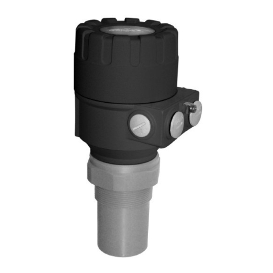
- Page 1 ® Echotel Series 335/338 Compact Ultrasonic Transmitter INSTALLATION PROGRAMMING MANUAL...
-
Page 2: Table Of Contents
C O N T E N T S INTRODUCTION................................2 ORDER CODES ................................2 TECHNICAL DATA................................ 3 Data of Echotel for liquids ................................3 INSTALLATION................................4 Liquid Level Measurement ................................4 Open Channel Flow Measurement ..............................5 Electrical Connection ..................................5 PROGRAMMING ................................ -
Page 3: Introduction
= General purpose IP 67 Mounting: 2" NPT 2" BSP Transducer Material: = Polypropylene = Kynar Order Codes for Accessories: 046 – 8108 - 001 : Local Indicator for Echotel 335/ 338 series 013 – 6165 - 001 : Magnetic Screwdriver - Calibration tool... -
Page 4: Technical Data
-25°C … +60°C PBT fibre-glass reinforced plastic, flame-retardant Housing material (DuPont Dimensions of Echotel 338/335 Echotel 338: PP, PVDF, PTFE Echotel 335: PP, PVDF, PTFE ~56.5 ~56.5 2 pcs Pg16 2 pcs Pg16 2x NPT1/2" 2x NPT1/2" BSP or BSP or or NPT 2"... -
Page 5: Installation
D min ( in mm) L in Echotel 338 Echotel 335 In case of closed tanks containing chemicals or other liquids creating fume/gases above the liquid surface especially for outdoor tanks exposed to the sun, a strong reduction of the nominal measuring range of the ultrasonic device is to be considered during device selection. -
Page 6: Open Channel Flow Measurement
4.2 Open Channel Flow Measurement For ultimate accuracy, install the sensor as close as possible above the expected maximum water level (see minimum measuring • range). Install the device upstream in a place defined by the characteristics of overflow and metering channel along the longitudinal axis of •... -
Page 7: Touch-Magnet Programming (Only For Level Transmitters For Liquids)
5.1 Touch-Magnet Programming The following can be programmed: with the supplied magnetic calibration tool – screwdriver PN°013-6165- 001: • Assignment of the 4 mA analogue output to a required e.g. min. level / max. distance • Assignment of the 20 mA analogue output to a required magnet e.g. - Page 8 Programming relay switch-off point (the level where relay becomes de-energised) Place the Echotel at a distance to the target corresponding to the required switch-off point. (Do not forget to check valid Echo!) Action LED indication 1) Place magnet to symbol “A” =Programming mode 2) Place magnet to symbol “B”...
-
Page 9: Programming Of The Echotel By The 046-8108-001 Programming Module
5.2 Programming of the Echotel by the 046-8108-001 Programming Module The 046-8108-001 supports 3 separately accessible programming modes representing 3- layers of programming complexity, depending on user choice. PLUG-IN PROGRAMMER Full Current Output QUICKSET Parameter Scaling Access Current Output Scaling (5.2.4) Recommended as a simple and fast way to modify the scaling of the current output. -
Page 10: Programming With The 046-8108-001 Programming Module
5.2.2 Programming with the 046-8108-001 Programming Module Programming will be performed by pressing one or two keys (simultaneously). Single key pressing Press key ENTER - to save parameter address and go to parameter value to return from parameter value to parameter address Press NEXT to move the blinking of the digit to the left Press UP to increase value of the blinking digit Press DOWN to decrease value of the blinking digit... -
Page 11: Current Output Scaling
5.2.4 Current Output Scaling This programming mode is the simple and fast way to modify the scaling of the current output. For changing all parameters other than those assigned to 4 and 20 mA use either the QUICKSET (5.2.2). or the Full Parameter Access (5.2.3). Current Output Scaling mode is useful for re-scaling i.e. -
Page 12: Quickset
5.2.5 QUICKSET Recommended as a simple and fast way to start up Echotel. QUICKSET programming is aided by 8 screens to set the 8 basic parameters of the device if the required application is uncomplicated level metering, recommended for liquids only. The instructions of this programming mode are also to be found, below the screw cover, on the front panel of the Echotel. -
Page 13: Full Parameter Access
5.2.6 Full Parameter Access To access all features provided by the Echotel. Description of all parameters can be found under the chapter “Parameter” (Chapter 6.). Keys Function ENTER + NEXT Enter or exit Full Parameter Access programming mode. (press for 3 seconds) In this programming mode, the display will indicate: yy is the Parameter Address yy:xxxx... - Page 14 P01: - ba Measurement Mode Display, current output and the switching points of the relays will be interpreted in the engineering units of the (measured or calculated) process value corresponding to the programmed measurement mode. On the other hand the higher the “a” of the programmed parameter value the more (measured or calculated) process values can be displayed on the screen.
- Page 15 Close end blocking (programmed value of P05 DEFAULT value of P05)) DIST=distance (measured) Programmed measurement range of the application LEV=level (calculed; P04-DIST) VOL=volume (calculated from DIST LEV) Far end blocking Basic conception and elements of the ultrasonic measurement P04: Maximum measuring distance The maximum measuring distance is the only one parameter that has to be programmed for each application other than distance measurement mode.
- Page 16 Level transmitters with PP or PVDF transducers for liquids (m/ft) Echotel 338 0,25 / 0,82 Echotel 335 0,35 / 1,2 FACTORY DEFAULT: automatic dead band control P06: Far-end blocking A). Level measurement Far end blocking is used to neglect incorrect level/volume readings and output actions below a pre-set level.
-
Page 17: Current Output
6.2 Current Output P10: Value (of distance, level, volume or flow) assigned to 4 mA current output P11: Value (of distance, level, volume or flow) assigned to 20 mA current output Values are interpreted according to P01(a). Please note that in case of programming for (LEV or VOL) % measurement the min and max value has to be entered in the relevant engineering units of LEV (m, ft) or VOL (m , ft Assignment can be made so that the proportion between the change of the (measured or calculated) process value and the... -
Page 18: Measurement Optimisation
6.4 Measurement Optimisation P20: - - - a Damping Use this parameter to reduce unwanted fluctuation of the display and output. Damping Echotel 335 / 338 time None/moderate Heavy/dense fume or (seconds) fume or waves turbulent waves no filter Recommended for testing only... - Page 19 P25: - - - a Selection of Echo within the measuring window A so-called measuring window is formed around the echo signal. The position of this measuring window determines the flight time for calculation of the distance of the target. (the picture below can be seen on the test oscilloscope) Received Echo 1.
- Page 20 P31: Sound velocity at 20_C (m/sec or ft/sec depending on P00(c) ) Use this parameter if the sound velocity in the gases above the measured surface differs largely from that of in air. Recommended for applications where the gas is more or less homogeneous. If it is not, the accuracy of the measurement can be improved using the 32-point linearisation (P48, P49).
-
Page 21: Volume Calculation
6.5 Volume Calculation P40: - - ba Tank/silo shape Tank/silo shape Also to be set Standing cylindrical tank shape: value of “b” as below bottom P40(b), P41 Standing cylindrical tank/silo with conical bottom P41, P43, P44 Standing rectangular tank/silo (with chute) P41, P42, (P43, P44, P45) Lying cylindrical tank shape: value of “b”... - Page 22 P46 is always the distance between the transducer face and the level, where the volume flow is 0. FACTORY DEFAULT: Flume / Weir Dimensions P40= 00 Magnetrol Parshall flumes (GPA1P1 … GPA-1P9) For further details see the Manual of the Parshall flume Sensor...
- Page 23 15cm P40= 13 Khafagi Venturi flume /s]= P42*1.744*h + 0.091*h Sensor Sensor P40= 14 Bottom step weir 0.0005 < Q[m /s] < 1 0.3 < P42[m] < 15 0.1 < h[m] < 10 /s]= 5.073*P42*h Accuracy: ± P40= 15 Suppressed rectangular or BAZIN weir 0.001 <...
-
Page 24: 32-Point Linearisation Curve
6.7 32-Point Linearisation Curve P47: - - - a Linearisation Linearisation OFF (FACTORY DEFAULT) P48: Linearisation table Linearisation is the method of assigning (calibrated or calculated) level, volume or flow to values measured by the transmitter. It can be used eg if the sound velocity is unknown (LEVEL⇒LEVEL) or in case of a vertical cylindrical tank (LEVEL ⇒... -
Page 25: Additional Open Channel Flow Metering Features
P70: Number of Echoes / Echo Map Number of Viewing this parameter gives the echoes in number of echoes detected by the the echo map NEXT system. Entering this parameter will save the actual echo map, and the distance and amplitude of these yy : xxxx yy : xxxx ENTER... -
Page 26: Simulation Mode
6.11 Simulation Mode This function enables the user to test the settings of the outputs. The Echotel can simulate a static or continuos change of level, according to the preset simulation parameters. Set the required simulation by programming P84, P85, P86 and P87. P84: - - - x Simulation Mode LEV [m] Simulation type... -
Page 27: Sound Velocities In Different Gases
SOUND VELOCITIES IN DIFFERENT GASES The following table contains the sound velocity of various gases measured on 20°C. Gases Sound Velocity (m/s) Acetaldehyde 252.8 Acetylene 340.8 Ammonia 429.9 Argon 319.1 Bensol 183.4 Carbon dioxide 268.3 Carbon monoxide 349.2 Carbon tetrachloride 150.2 Chlorine 212.7... - Page 28 Magnetrol Heikensstraat 6 – 9240 Zele (Belgium) Phone : ++32 (0)52 45 11 11 – Fax : ++32 (0)52 45 09 93 E-mail : info@magnetrol.com – web : www.magnetrol.com BULLETIN N°: BE 51-638.0 EFFECTIVE: JULY 2001 UNDER RESERVE OF MODIFICATIONS...
Need help?
Do you have a question about the Echotel 335 and is the answer not in the manual?
Questions and answers