Table of Contents
Advertisement
Quick Links
Advertisement
Table of Contents

Related Manuals for Pro-face GP-2401T


Summary of Contents for Pro-face GP-2401T
- Page 1 GP-2401/2501/2601 Series User Manual (Pro-Designer Compatible)
- Page 2 Preface Thank you for purchasing the Pro-face GP-2401/2501/2601 Series programmable operator interface (hereafter referred to as the “GP unit”). GP-2401/2501/2601 Series units allow you to use the CF Card without attaching separately sold expansion units. Please read this manual carefully as it explains, step by step, how to use the GP correctly and safely.
-
Page 3: Table Of Contents
Interface Specifications ................2-6 2.3.1 Serial Interfaces (COM1) ..............2-6 Part Names and Functions ................. 2-8 Dimensions ....................2-10 2.5.1 GP-2401T External Dimensions............. 2-10 2.5.2 GP-2501T External Dimensions............. 2-11 2.5.3 GP-2601T External Dimensions............. 2-12 2.5.4 Panel Cut Dimensions ..............2-13 2.5.5 Installation Fasteners ............... -
Page 4: Preface
Preface CHAPTER 3 INSTALLATION AND WIRING Installation ....................3-1 3.1.1 Installation Procedures ..............3-1 Wiring Cautions ................... 3-6 3.2.1 Connecting the Power Cord .............. 3-6 3.2.2 Connecting the Power Supply ............3-8 3.2.3 Grounding ..................3-9 3.2.4 I/O Signal Line Placement ..............3-9 Tool Connector ................... -
Page 5: Essential Safety Precautions
Preface Essential Safety Precautions This manual includes procedures that must be followed to operate the GP cor- rectly and safely. Be sure to read this manual and any related materials thoroughly to understand the correct operation and functions of this unit. Safety Icons Throughout this manual the following icons are provided next to GP operation procedures requiring special attention, and provide essential safety information. - Page 6 Preface WARNINGS • Do not create switches used to control machine safety operations, such as an emergency stop switch, or a GP touch screen icon. Be sure to install these switches as separate hardware switches, otherwise severe bodily injury or equipment damage can occur. •...
- Page 7 Preface WARNINGS Battery Replacement • The GP uses a lithium battery for backing up its internal clock data. If the battery is incorrectly replaced, the bat- tery may explode. To prevent this, please do not replace the battery yourself. When the battery needs to be re- placed, please contact your local GP distributor.
- Page 8 Preface CAUTIONS Wiring • Ground the GP’s FG line separately from other units’ FG lines. Putting these FG lines too close may cause an elec- tric shock or unit malfunction. Be sure to use a grounding resistance of 100Ω Ω Ω Ω Ω or less and a 2mm or thicker wire, or your country’s applicable standard.
-
Page 9: General Safety Precautions
Preface General Safety Precautions • Do not strike the touch panel with a hard or pointed object, or press on the touch panel with too much force, since it may damage the touch panel or the display. • Do not install the GP where the ambient temperature can exceed the allowed range. - Page 10 Preface About the GP’s Display Panel • The GP’s currently displayed data, its voltage and brightness set- ting each affect the intensity of Contouring. (i.e, when some parts of the screen are brighter than others, creating a wavelike pattern) • There are minute grid-points (dark and light) on the Display Panel’s surface.
-
Page 11: Gp-2401/2501/2601 Series Model Names
Preface GP-2401/2501/2601 Series Model Names The GP-2401/2501/2601 Series refers to the following GP model numbers: Series Model Name Model Type Comments UL/c-UL (CSA) GP-2401 GP-2401T GP2401-TC41-24V Approved, Series CE Marked GP2000 GP-2501 GP-2501T GP2501-TC11 Series Series GP-2501S GP2501-SC11 GP-2601 GP-2601T... -
Page 12: Ul/C-Ul (Csa) Application Notes
Preface UL/c-UL (CSA) Application Notes The GP2401-TC41-24V is UL/c-UL (CSA) listed products. (UL file No.E182139) The GP2501-TC11 , GP2501-SC11 , GP2601-TC11 , are UL/c-UL (CSA) listed products. (UL file No.E231702) This unit conforms as a product to the following standards: Standards UL registered Model... -
Page 13: Ce Marking Notes
Preface UL1604 Conditions of Acceptability and Handling Cautions: 1. Power, input and output (I/O) wiring must be in accordance with Class I, Divi- sion 2 wiring methods - Article 501- 4(b) of the National Electrical Code, NFPA 70 within the United States, and in accordance with Section 18-152 of the Canadian Electrical Code for units installed within Canada. -
Page 14: Revision Version
Preface Revision Version The revision version can be determined by the identification label or revision stickers that are placed on the main unit of the GP. The characters and numerals in the “REV” area that are replaced with asterisks (*), or marked with a marker indicate the revision version. - Page 15 Memo GP-2401/2501/2601 Series User Manual...
-
Page 16: System Design
1. System Design Chapter 2. Accessories Introduction System Design The following diagram represents the standard items connected to the GP. 1.1.1 GP-2401/2501/2601 Series System Design GP RUN Mode Peripherals RUN Mode Edit Mode GP Unit CF Card GP077-CF20, GP077-CF30 RS-232C Cable GP410-IS00-O *1 Host Controller RS-422 Cable... - Page 17 Chapter 1 - Introduction GP Edit Mode Peripherals GP Interfaces PLC Interfaces GP Unit (1) Tool Connector (4) RS-232C Port (2) CF Card (5) RS-422 Port (3) Serial Interface (COM1) (6) Programming Con- sole Port Data Transfer Cable GPW-CB02 Pro-Designer Personal Computer *1 CF Card...
-
Page 18: Accessories
Chapter 1 - Introduction Accessories All optional equipment listed here is produced by Digital Electronics Corporation. Available Software Product Name Model No. Description PS-DWE01-V40 Software to be used to create the screen Pro-Designer data. Installed in a personal computer. Ver. 4.0 or later Tool Connector Product Name Model No. - Page 19 Disposable, dirt-resistant sheet for the (GP-2501T, GP-2501S, GP's screen. T he GP's touch panel can Screen Protection Sheet GP-2601T) be operated with this cover sheet PS400-DF00 (GP-2401T ) attached. (5 sheets/set) Maintenance Items They are available separately as optional maintenance items. Description Product Name Model No.
-
Page 20: Chapter 2 Specifications
1. General Specifications 4. Part Names and Functions Chapter 2. Functional Specifications 5. Dimensions 3. Interface Specifications Specifications General Specifications 2.1.1 Electrical GP2501-TC11/GP2501-SC11/GP2601-TC11 AC 100V AC 100V to AC240V Input Voltage AC85V to AC132V AC85V to AC265V Rated Voltage 50VA or less (ACIN100V) 50VA or less Power Consumption 85VA or less (ACIN240V) -
Page 21: Environmental
Chapter 2 - Specifications 2.1.2 Environmental GP-2401T GP-2501T GP-2501S GP-2601T Ambient Operating C to +50 Temperature C to +60 Storage Temperature 10%RH to 90%RH Ambient Humidity (Non condensing, wet bulb temperature: 39 C or less) Atmosheric Endurance 800hPa to 1114hPa (2000 meters or lower) (GP Operation Altitude) 0.1mg/m... -
Page 22: Structural
Chapter 2 - Specifications 2.1.3 Structural GP-2401T GP-2501T GP-2501S GP-2601T 100 Ω or less, or your country's applicable standard Grounding Equivalent to IP65f (JEM 1030) Ratings NEMA#250 Type4X/12 (For front panel of installed unit) 1.7 kg (5.5lb) or less 3.5kg (7.7lb) or less... -
Page 23: Functional Specifications
Chapter 2 - Specifications Functional Specifications 2.2.1 Display GP-2401T GP-2501T GP-2501S GP-2601T TFT type color LCD STN type color LCD TFT type color LCD Type 640 x 480pixels 800 x 600pixels Resolution W211.2mm [8.34in.] x W149.8mm [5.90in.] x W246mm [9.69in.] x Effective Display H158.4mm [6.24in.]... -
Page 24: Clock
Chapter 2 - Specifications 2.2.3 Clock GP-2401T GP-2501T GP-2501S GP-2601T 40 x 30 keys 32 x 24 keys/screen /screen Resolution 1 or 2 point push - selectable 1 or 2 point push- selectable + 65 seconds/ month (at room temperature) Clock Accuracy The GP’s internal clock has a slight error. -
Page 25: Interface Specifications
Chapter 2 - Specifications Interface Specifications 2.3.1 Serial Interfaces (COM1) This interface can be either RS-232C or RS-422. Connects GP to Host (PLC). This interface uses a socket-type connector. Pin Assignments Pin # Signal Name Condition Frame ground Send data (RS-232C) (D-Sub 25pin female) Receive data (RS-232C) Request send (RS-232C) - Page 26 Chapter 2 - Specifications When creating your own cable, follow the instructions listed below: <With RS-422> • The following pairs of pin numbers must be connected to each other. #18 (CSB) <—> #19 (ERB) #21 (CSA) <—> #22 (ERA) • When connecting the RS-422 cable and the #9 (TRMX) and #10 (RDA) points, a termination resistance of 100Ω...
-
Page 27: Part Names And Functions
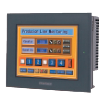
Chapter 2 - Specifications Part Names and Functions A: Display Panel The GP monitor screen displays the screen setup and corresponding host (PLC) data. GP-2401T TFT type color LCD GP-2501T TFT type color LCD GP-2501S STN type color LCD GP-2601T... - Page 28 Chapter 2 - Specifications H:CF Card Slot Insert a CF Card in this slot. I : Dip Switches Bottom Dip Switch Function Note This Dip switch Startup from Startup from CF Card with setting controls CF Card is CF Card is startup data the startup from a enabled.
-
Page 29: Dimensions
2.5.1 GP-2401T External Dimensions Unit: mm [in.] 204 [8.03] 60 [2.36] 215 [8.46] 8 [0.31] Side Front The following drawing shows the GP-2401T Series unit with installation fasten- ers. 135 [5.31] 67.5 [2.66] 60 [2.36] 215 [8.46] 8 [0.31] Front... -
Page 30: Gp-2501T External Dimensions
Chapter 2 - Specifications 2.5.2 GP-2501T External Dimensions Unit: mm [in.] 301 [11.85] 317 [12.48] 58 [2.28] 8 [0.31] Front Side The following drawing shows the GP-2501T/2501S Series unit with installation fasteners. 270 [10.63] 135 [5.31] 58 [2.28] 317 [12.48] 8 [0.31] Front Side... -
Page 31: Gp-2601T External Dimensions
Chapter 2 - Specifications 2.5.3 GP-2601T External Dimensions Unit: mm [in.] 301 [11.85] 317 [12.48] 58 [2.28] 8 [0.31] Front Side The following drawing shows the GP-2601T Series unit with installation fasten- ers. 270 [10.63] 135 [5.31] 58 [2.28] 317 [12.48] 8 [0.31] Side Front... -
Page 32: Panel Cut Dimensions
Chapter 2 - Specifications 2.5.4 Panel Cut Dimensions GP-2401T Unit: mm [in.] +0.04 204.5 0 [8.05 4-R3 or less GP-2501T/2501S/2601T Unit: mm [in.] +0.04 301.5 0 [11.87 4-R3 or less 2.5.5 Installation Fasteners Unit: mm [in.] 16[0.63] 31[1.22] 19.5[0.77] GP-2401/2501/2601 Series User Manual... - Page 33 Memo GP-2401/2501/2601 Series User Manual 2-14...
-
Page 34: Chapter 3 Installation And Wiring
Be sure to change the gasket periodically, or when scratches or dirt become visible. • Be sure to use gasket model PS400-WP00-MS (GP-2401T)/GP570- WP10-MS (GP-2501T/2501S/2601T). • Be sure the gasket’s seam is not inserted into any of the unit’s cor- ners, only in the straight sections of the groove. - Page 35 Chapter 3 - Installation and Wiring Creating a Panel Cut Create the correct sized opening required to install the GP, using the installation dimensions given. 2.5.4 GP Panel Cut Dimensions The installation gasket, installation brackets and attachment screws are all re- quired when installing the GP.
- Page 36 Chapter 3 - Installation and Wiring • Be sure that the ambient operation temperature and the ambient humidity are within their designated ranges. (When installing the GP in a cabinet or enclosure, the term “ambient operation temperature” indicates the cabinet or enclosure’s internal temperature. •...
- Page 37 2) Insert the installation fasten- ers into the GP’s insertion slots, at the top and bottom of the unit. (total: 4 slots) Do not use the attach- ment holes in the GP-2401T middle of side panels. GP-2501T/GP-2501S/GP-2601T GP-2401/2501/2601 Series User Manual...
- Page 38 GP unit. Depending on the panel condition, you can improve moisture resistant effect by in- creasing the number of installation fasteners. However, since GP-2401T has only four installation holes, you cannot increase it in this case. GP-2401/2501/2601 Series User Manual...
-
Page 39: Wiring Cautions
Chapter 3 - Installation and Wiring Wiring Cautions 3.2.1 Connecting the Power Cord WARNINGS • To avoid an electric shock, be sure the power cord is unplugged from the power outlet when connecting the power terminals to the GP unit. •... - Page 40 Chapter 3 - Installation and Wiring Connecting the Power Supply Terminals GP2501-TC11, GP2501-SC11, GP2601-TC11 Power Terminal Block AC Input Live Line AC Input Neutral Line Grounding Terminal connected to the GP chassis. GP2401-TC41-24V Positive electrode Negative electrode Grounding T erminal connected to the GP chassis.
-
Page 41: Connecting The Power Supply
Chapter 3 - Installation and Wiring 3.2.2 Connecting the Power Supply • If the supplied voltage exceeds the Twisted Lines GP unit’s range, connect a voltage voltage GP unit transformer. transformer Chapter 2 Specifi- cations for the allowable voltage range. Twisted Lines noise GP unit... -
Page 42: Grounding
Chapter 3 - Installation and Wiring 3.2.3 Grounding CAUTION Do not use common grounding, since it can lead to an acci- dent or machine breakdown. Connect the FG terminal found at (a) Exclusive Grounding (BEST) the back of the GP to an exclusive ground. -
Page 43: Tool Connector
To prevent an electric shock, unplug the GP unit’s power cord from the main power supply prior to attaching or de- taching any connector(s) to or from the GP. Bottom Face Rear Face GP-2501T/GP-2501S/ GP-2601T GP-2401T Tool Connector GP-2401/2501/2601 Series User Manual 3-10... -
Page 44: Cf Card Installation And Removal
Chapter 3 - Installation and Wiring CF Card Installation and Removal CAUTIONS When using the GP Unit and a CF Card, follow the precau- tions below: • Prior to inserting or removing a CF Card, be sure to turn the GP unit’s CF Card ACCESS switch OFF and to confirm that the ACCESS lamp is not lit. - Page 45 Use the following steps to insert the CF Card in the GP. (The illustrations below show the procedures for the GP-2501T/GP-2501S/GP- 2601T models. However, these procedures are also the same for the GP-2401T.) 1) Slide the CF Card Cover in the direc- tion shown here, then upwards to open the cover.
-
Page 46: Cf Card Handling
• Depending on the setup of your PC, it is possible that the Card Reader may not operate correctly. • All of Pro-face’s CF Card operation testing has been performed using the follow- ing equipment. The connection between a personal computer and the CF Card reader has been tested using a Windows®... -
Page 47: Attaching The Screw Lock Terminal Block
GP unit’s AUX I/O I/F. (The illustrations below show the procedures for the GP-2501T/GP-2501S/GP- 2601T models. However, these procedures are also the same for the GP-2401T.) 1) Loosen the set screws of each de- sired Screw Lock Terminal Block pin. -
Page 48: Chapter 4 Settings
1. Types of Settings Chapter Settings Types of Settings The settings required for the GP unit, when starting Runtime or when in RUN mode, are found in the Settings Menu. To call up this menu: 1. Connect the GP unit’s power supply. Pro-Designer Runtime must be installed. -
Page 49: Offline
Chapter 4 - Settings Offline - Network - Buzzer - Backlight - Self Test - OP. Switch System - Stylus - Date/Time - Restart - Ver. Info. - Language - Memory GP-2401/2501/2601 Series User Manual... - Page 50 Chapter 4 - Settings 4.1.1 Offline Network This cannot be set with GP-2401/2501/2601 Series units. Touch Buzzer The following buzzer sound settings are available. The factory setting is [Press Touch Object]. • [None] Selecting this will turn the buzzer off. •...
- Page 51 Chapter 4 - Settings Backlight Control Here, three selections (modes) are available. • Wait To preserve the GP unit’s screen display elements and extend the life of the backlight, the backlight can be set to automatically turn off after a designated period of inactivity (idle time) elapses.
- Page 52 Chapter 4 - Settings 4.1.2 System Stylus This setting is not required for GP series units. Date/Time Sets the GP unit’s date and time. Setting Procedure 1. In the [Settings] menu, touch the [System] tab. 2. Touch the [Date/time] icon. 3.
- Page 53 Chapter 4 - Settings Memory Displays the total amount of memory, and the amount of memory currently being used. Setting Procedure 1. In the [Settings] menu, touch the [System] tab. 2. Touch the [Memory] icon. GP-2401/2501/2601 Series User Manual...
-
Page 54: Chapter 5 Troubleshooting
1. Troubleshooting Checklists Chapter 2. SELF TEST Troubleshooting This section explains how to find and resolve GP unit problems. The GP unit can be connected to a wide range of devices, including a host (PLC), however, this manual will not discuss every possible device, or problem. For problems not directly related to the GP unit, refer to that device’s manual. -
Page 55: No Display
Chapter 5 - Troubleshooting 5.1.1 No display Check Item/Operation Countermeasure Are all Pro-Designer screens sent If not, send to the GP. to the GP unit? Is the [Initial Panel ID] set up If not, enter the [Initial Panel ID] and re-send correctly in Pro-Designer? the screen data. -
Page 56: Self Test
Chapter 5 - Troubleshooting SELF TEST The GP unit is equipped with a number of self diagnosis features used to check its System and Interfaces for any problems. 5.2.1 SELF TEST item list - Char. Pattern - Disp Pattern - Touch Panel *1*2 - COM 1 - COM 2... -
Page 57: Self Test - Details
Chapter 5 - Troubleshooting 5.2.2 SELF TEST - details This section explains the contents of SELF TEST. Char.Pattern Checks each font’s pattern and kanji-characters’ROM. Used when kanji-characters do not display. If there is no error, the message [OK] will appear, if there is an error, the message [NG] will appear. -
Page 58: Chapter 6 Maintenance
Installation Gasket Attachment Procedure (The illustrations below show the procedures for the GP-2501T/GP-2501S/GP- 2601T models. However, these procedures are also the same for the GP-2401T.) 1) Place the GP on a flat, level surface facing the display face downwards. - Page 59 Chapter 6 - Maintenance 3) Attach the new gasket to the GP. Be sure to insert the gasket into the GP’s groove so that the gasket’s groove sides are vertical. 4) Check if the gasket is attached to the GP correctly. •...
-
Page 60: Periodic Check Points
Chapter 6 - Maintenance Periodic Check Points To keep your GP unit in its best condition, please inspect the following points periodically. GP Operation Environment • Is the operating temperature within the allowable range (0 C to 50 C )? •... -
Page 61: Replacing The Backlight
Chapter 6 - Maintenance Replacing the Backlight When the unit’s backlight burns out, the unit’s status LED will turn orange. If the OFFLINE menu’s “USE TOUCHPANEL AFTER BACKLIGHT BURNS OUT” feature is set to “NO”, the GP’s touch panel will be disabled. GP2000 Series units use a CFL, long-life type backlight.
Need help?
Do you have a question about the GP-2401T and is the answer not in the manual?
Questions and answers