Table of Contents
Advertisement
Advertisement
Table of Contents

Subscribe to Our Youtube Channel
Related Manuals for Pro-face ST3000 Series


Summary of Contents for Pro-face ST3000 Series
-
Page 2: Preface
Preface Thank you for purchasing Pro-face’s ST3000 Series Programmable Operator Interface (Hereafter referred to as the “ST unit”). Before operating your ST unit, be sure to read this manual to familiarize yourself with the ST unit’s operation procedures and features. -
Page 3: Essential Safety Precautions
Essential Safety Precautions All safety-related procedures stated in this document must be followed to operate the ST correctly and safely. Be sure to read this and any related documents thoroughly to understand the correct operation and functions of the ST unit. Safety Icons Throughout this manual, these icons provide essential safety information for ST operation procedures requiring special attention. - Page 4 Be sure to design your system so that a communication fault between the ST and its host controller will not cause equipment to malfunction. This is to prevent any possibility of bodily injury or equipment damage. After the ST unit’s backlight burns out the touch panel is still active, unlike the ST unit’s “Standby Mode”. If the operator fails to notice that the backlight is burned out and touches the panel, a potentially dangerous machine operation error can occur.
- Page 5 Installation Be sure all cable connectors are securely attached to the ST unit. A loose connection may cause incorrect input or output signals. Wiring Be sure to ground the ST unit’s FG wire separately from other equipment FG lines. Also, be sure to use a grounding resistance of 100 or less and a 2mm or thicker wire, or your country’s applicable standard.
- Page 6 Do not use paint thinner or organic solvents to remove dirt or oil from the ST unit’s surface. Instead, use a soft cloth moistened with a diluted neutral detergent. Do not use or store the ST in areas with direct sunlight, since the sun’s ultraviolet rays may cause the LCD’s quality to deteriorate.
- Page 7 LCD Panel Usage Precautions • The LCD panel’s liquid contains an irritant. If the panel is damaged and any of this liquid contacts your skin, immedi- ately rinse the area with running water for at least 15 minutes. If the liquid gets in your eyes, immediately rinse your eyes with running water for at least 15 minutes and consult a doctor.
-
Page 8: Information Symbols
Information Symbols This manual uses the following icons: Indicates a warning or a product limitation. Be sure to follow the instructions given with this icon to ensure the safe operation of the ST. Screen Editor Indicates the GP-Pro EX software. Abbreviation for Programmable Logic Controller. -
Page 9: St3000 Series Model Name Indication
ST3000 Series Model Name Indication Model name A ST 3 ∗ ∗ 1 - ∗ 1 - ∗∗∗ ST-3200 series (3.8-inch): QVGA (320 x 240 dots) ST-3200 series SIO type ST-3200 series MPI type Monochrome Amber/Red LCD DC type power supply is used. -
Page 10: St3000 Series Model Names
ST3000 Series Model Names The term “ST3000” Series refers to the following ST model numbers: Series Model Product number AST-3201A (SIO) AST3201-A1-D24 ST3000 series ST-3200 series AST-3211A (MPI) AST3211-A1-D24... -
Page 11: Package Contents
Package Contents The following items are included in the ST unit’s package. Before using the ST, please check that all items listed here are present. English and Japanese Installation ST Unit: 1 Warning/Caution Information Guides (One of each) Installation Warning/ Guide Caution Information... -
Page 12: Ul/C-Ul Approval
UL/c-UL Approval The following units are UL/c-UL listed products. (UL File No.E220851) Product Model No. UL/c-UL Registration Model No. AST3201-A1-D24 3580205-01 AST3211-A1-D24 3580205-02 This product conforms to the following standards: • UL508 Industrial Control Equipment • CSA-C22.2 No.142-M1987 (c-UL Approval) Standard for Process Control Equipment <Cautions>... -
Page 13: Ce Marking
CE Marking The following units are CE marked products complying with the EMC Directive. They comply with EN55011 Class A, EN61131-2. AST3201-A1-D24 AST3211-A1-D24 About Revision The nameplate on the ST has the revision code of the ST. In the example below, the asterisk, which is placed at the “A” position, shows that the revision code is “A”. -
Page 14: Table Of Contents
Contents Preface ........................1 Essential Safety Precautions..................2 Information Symbols....................7 ST3000 Series Model Name Indication..............8 ST3000 Series Model Names ................... 9 Package Contents ....................10 UL/c-UL Approval .....................11 CE Marking......................12 About Revision ......................12 Chapter 1 Overview 1.1 System Design.................... - Page 15 Chapter 5 Maintenance 5.1 Cleaning the Display..................5-2 5.2 Periodic Check Points..................5-3 5.3 Replacing the Installation Gasket ..............5-4 5.4 Replacing the Backlight .................. 5-6...
-
Page 16: Chapter 1 Overview
Overview 1. System Design 2. Accessories This chapter describes the peripheral devices that can be connected to the ST Series units. - Page 17 ST3000 Series Hardware Manual 1.1 System Design The following diagram illustrates the standard range of items that can be connected to ST3000 Series units. For host controller (PLC, etc.) connection information, refer to the “GP-Pro EX Device/PLC Connection Manual”. ST RUN Mode Peripherals...
- Page 18 Chapter 1 Overview RS-232C Cable RS-232C CA3-CBL232/5M-01 Isolation Unit CA3-ISO232-01 Mitsubishi PLC Q-Series Link Cable CA3-CBLLNKMQ-01 Host Controller PLC etc. Omron PLC SYSMAC Link Cable CA3-CBLSYS-01 Mitsubishi PLC Q-Series Connection Cable CA3-CBLQ-01 RS-422 Cable RS-232C CA3-CBL422/5M-01 Isolation Unit CA3-ISO232-01 RS-422 Cable COM Port CA3-CBL422-01 Conversion Adapter...
- Page 19 ST3000 Series Hardware Manual Siemens TTY Converter Cable CA6-CBLTTL/5M-01 MPI Cable ST03-A2B-MPI21-PEE Mitsubishi PLC FX-Series Connection Cable CA3-CBLFX/1M-01 CA3-CBLFX/5M-01 Mitsubishi PLC A-Series Connection Cable CA3-CBLA-01 Host Controller PLC etc. RS-422 Cable CA3-CBL422/5M-01 COM Port RS-422 Cable Conversion CA3-CBL422-01 Adapter CA3-ADPCOM-01...
- Page 20 (Commercial type) ST Interfaces (1) USB Host Interface For supported models, refer to Pro-face’s support site “Otasuke Pro!” http://www.pro-face.com/otasuke/ You can connect to this site by clicking the GP-Pro EX’s [Help (H)] menu - [Connect to Support Site- “Otasuke Pro!” (O)] command.
-
Page 21: Accessories
ST3000 Series Hardware Manual 1.2 Accessories All accessories listed here are produced by Pro-face. Serial Interface Item Product Name Model No. Description Connects Mitsubishi PLC A-Series (or RS-232C Cable CA3-CBL232/5M-01 (5m) other host controller) to the ST. (RS-232C) Connects a host controller to the ST. - Page 22 Reader for the RS-232C communication method. *1. For supported models, refer to Pro-face’s support site “Otasuke Pro!” http://www.pro-face.com/otasuke/ You can connect to this site by clicking the GP-Pro EX’s [Help (H)] menu - [Connect to Support Site- “Otasuke Pro!” (O)] command.
- Page 23 ST3000 Series Hardware Manual Option Items Product Name Model No. Description Disposable, dirt-resistant sheet for the ST Screen Protection Sheet CA6-DFS4-01 unit’s screen. (5 sheets/set) (Hard type) Maintenance Items Product Name Model No. Description Installation Fastener CA3-ATFALL-01 Used to install the ST into a solid panel.
-
Page 24: Chapter 2 Part Names And Functions
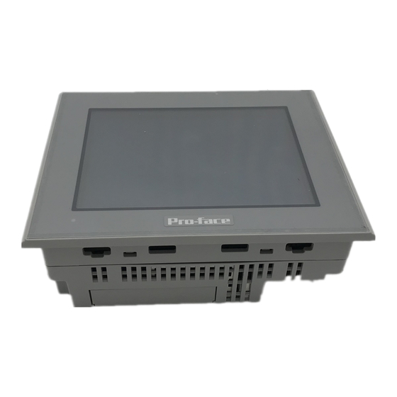
Part Names and Functions 1. ST-3200 Series This chapter describes the names and functions of the components of the ST series. -
Page 25: St-3200 Series
ST3000 Series Hardware Manual 2.1 ST-3200 Series A: Status LED This LED indicates the ST’s status, e.g. power input, firmware RUN status or backlight condition. ST Operation Normal operation (power Green (lit) is ON.) or OFFLINE operation. Orange During software startup. - Page 26 Specifications 1. ST-3200 Series This chapter describes the general specifications, functions, interfaces and external drawings of the ST.
-
Page 27: General Specifications
ST3000 Series Hardware Manual 3.1 ST-3200 Series 3.1.1 General Specifications Electrical Specifications Input Voltage DC24V Rated Voltage DC19.2 to 28.8V Allowable Voltage Drop 2ms (max.) Power Consumption 13W (max.) In-Rush Current 60A (max.) AC1000V 20mA for 1 minute Voltage Endurance (between charging and FG terminals) DC500V 10MΩ... - Page 28 Chapter 3 Specifications Structural Specifications Grounding resistance of 100Ω 2mm or thicker wire, Grounding or your country’s applicable standard. (Same for FG and SG terminals) Rating: Equivalent to IP65f NEMA #250 TYPE 4X/13 (Front surface at panel embedding) Structure Feature size: All-in-one Installation configuration: Panel embedding Cooling Method Natural air circulation...
-
Page 29: Performance Specifications
ST3000 Series Hardware Manual 3.1.2 Performance Specifications Performance Specifications AST-3201A AST-3211A Application FLASH EPROM 6MB SRAM 320K byte Data Backup Used lithium battery for backup memory COM1: RS232C COM1: RS232C Asynchronous Transmission Asynchronous Transmission Data Length: 7 bit/8 bit Data Length: 7 bit/8 bit... - Page 30 Chapter 3 Specifications Display Specifications Display Type Monochrome Amber/Red LCD Resolution W320 X H240 pixels Dot pitch W0.24mm[0.01in] X H0.24mm[0.01in] Effective Display W78.8mm[3.10in] X H59.6mm[2.35in] Area Color/Shade level Black and White (8 Shades) Backlight LED (Not replaceable) Brightness control 16 levels of adjustment available via touch panel Contrast Adjustment 8 levels of adjustment available via touch panel MTBF value: 50, 000hrs.
-
Page 31: Interface Specifications
ST3000 Series Hardware Manual 3.1.3 Interface Specifications This section describes the specifications of each interface of the ST Series unit. • The serial interface of the ST Series (except AST-3211A COM2) does not have an isolation function. When the host (PLC) unit is also not isolated, be sure to connect the #5 SG (Signal Ground) terminal to reduce the risk of damaging the RS232C/RS422/RS485 circuit. - Page 32 Chapter 3 Specifications AST-3201A Serial Interfaces (COM1) This interface is used to connect an RS232C cable. D-sub 9-pin plug connector is used. <ST unit side> ST Connector XM2C-0942-502LX <OMRON Co.> Interfit Bracket #4-40 inch screws are used. <Cable side> Recommended Cable Connector XM2D-0901 <OMRON Co.>...
- Page 33 ST3000 Series Hardware Manual Serial Interface (COM2) This interface is used to connect an RS422/RS485 serial cable. A D-sub 9-pin plug connector is used. <ST unit side> ST Connector XM2C-0942-502LX <OMRON Co.> Interfit Bracket #4-40 inch screws are used. <Cable side>...
- Page 34 Chapter 3 Specifications AST-3211A Serial Interface (COM1) This interface is used to connect an RS232C serial cable. A D-sub 9-pin plug connector is used. <ST unit side> ST Connector XM2C-0942-502LX <OMRON Co.> Interfit Bracket #4-40 inch screws are used. <Cable side> Recommended Cable Connector XM2D-0901 <OMRON Co.>...
- Page 35 ST3000 Series Hardware Manual Serial Interface (COM2) This interface is used to connect an RS485 (MPI only) serial cable. A D-sub 9-pin socket connector is used. <ST unit side> ST Connector XM3B-0942-502LX <OMRON Co.> Interfit Bracket #4-40 inch screws are used.
-
Page 36: Dimensions
Chapter 3 Specifications 3.1.4 Dimensions The following dimensions apply to ST-3200 Series units. Installation Fasteners Attached Dimensions Unit: mm[in.] 118[4.65] 139.3[5.48] 40[1.57] 130[5.12] 5[0.20] Left side Front Right side Bottom 3-11... - Page 37 ST3000 Series Hardware Manual Cable Attached Dimensions Unit: mm[in.] 83[3.27] 83[3.27] Front Left side Rear Right side Bottom • Depending on the type of connection cable used, the dimensions shown above will change. The dimensions given here are representative values and are intended for reference only.
- Page 38 Chapter 3 Specifications Panel Cut Dimensions Unit: mm[in.] +0.04 [4.67 118.5 Under 4-R3[0.12] Panel thickness area 1.6[0.06] to 5.0[0.20] Installation Fasteners Unit: mm[in.] 16[0.63] 16.6[0.65] 31[1.22] 3-13...
- Page 39 ST3000 Series Hardware Manual 3-14...
-
Page 40: Chapter 4 Installation And Wiring
Installation and Wiring 1. Installation 2. Wiring Precautions 3. USB Cable Clamp Attachment/Removal This chapter describes the installation, cable arrangement of the ST Series and its peripheral equipment. - Page 41 ST3000 Series Hardware Manual 4.1 Installation This section describes the procedures and precautions for installing the ST Series units. Check the Installation Gasket’s Seating It is strongly recommended that you use the installation gasket, since it absorbs vibration in addition to repelling water.
- Page 42 Chapter 4 Installation and Wiring Installation Requirement • For easier maintenance, operation, and improved ventilation, be sure to install the ST at least 100 mm [3.94 in.] away from adjacent structures and other equipment. Unit: mm[im.] [3.94] [3.94] [3.94] [3.94] [3.94] [3.94] [3.94]...
- Page 43 ST3000 Series Hardware Manual • When installing the ST in a slanted panel, the panel face should not incline more than 30°. 30° or less • When installing the ST in a slanted panel, and the panel face inclines more than 30°, the ambient temper- ature must not exceed 40°C.
- Page 44 Chapter 4 Installation and Wiring Installing the ST (1) Insert the ST into the panel cut, as shown. (2) Mount four pieces of the panel-mounting Installation Panel brackets on the right and left sides, or the top and bottom sides of the panel to secure the panel.
- Page 45 ST3000 Series Hardware Manual (3) Insert each of the fasteners shown below. Be sure to pull the fastener back until it is flush with the rear of the attachment hole. (4) Use a Phillips screwdriver to tighten each fastener screw and secure the ST in place.
-
Page 46: Connecting The Power Cord
Chapter 4 Installation and Wiring 4.2 Wiring Precautions This section describes the procedures and precautions for wiring power cords. 4.2.1 Connecting the Power Cord To avoid an electric shock, prior to connecting the ST unit’s power cord terminals to the power terminal block, confirm that the ST unit’s power supply is completely turned OFF, via a breaker, or similar unit. - Page 47 Power Connector (Plug) Specifications Insertion Direction − FG Grounding Terminal connected to the • The power supply connector (plug) is CA5-DCCNM-01 (made by Pro-face) or MSTB2,5/3-ST-5,08 (made by Phoenix Contact *1. For details, please contact your local Phoenix Contact distributor.
- Page 48 Chapter 4 Installation and Wiring Wiring When connecting the Power Cord, use the following items when performing wiring. (Items are made by Phoenix Contact.) Recommended Driver SZF 1-0.6x3.5 (1204517) AI 0.75-8GY (3200519) Recommended Pin AI 1-8RD (3200030) Terminals AI 1.5-8BK (3200043) AI 2.5-8BU (3200522) Recommended Pin CRIMPFOX ZA3 (1201882)
-
Page 49: Connecting The Power Supply
ST3000 Series Hardware Manual 4.2.2 Connecting the Power Supply This section describes the precautions for supplying a power voltage. Twisted-pair cord Constant Voltage • If the supplied voltage exceeds the ST unit’s range, Transformer connect a constant voltage transformer. Chapter 3 Specifications (page 3-1) Twisted-pair cord •... -
Page 50: Grounding
Chapter 4 Installation and Wiring 4.2.3 Grounding This section describes the precautions for grounding the ST unit. Do not use common grounding, since it can lead to an accident or machine breakdown. (a) Exclusive Grounding (BEST) • When supplying power to the ST unit, be sure to separate the Other input/output and power lines, as shown. -
Page 51: I/O Signal Line Placement
ST3000 Series Hardware Manual 4.2.4 I/O Signal Line Placement • Input and output signal lines must be separated from the power control cables for operating circuits. • If this is not possible, use a shielded cable and connect the shield to the ST unit’s frame. -
Page 52: Usb Cable Clamp Attachment/Removal
Chapter 4 Installation and Wiring 4.3 USB Cable Clamp Attachment/Removal This clamp is used to prevent the USB cable connected to the USB Host Interface on the bottom of the ST unit from being unplugged due to vibration or other causes. Attachment (1) Before starting the procedure, lift up the tab on both sides of the USB Holder and remove the USB Cover. - Page 53 ST3000 Series Hardware Manual (4) Attach the USB cover to fix the USB cable. Insert the USB cover into the tab of the USB holder. ST-3200 Series USB Cover • Check the up/down orientation of the USB cover to ensure that the USB cable is secured properly.
- Page 54 Maintenance 1. Cleaning the Display 2. Periodic Check Points 3. Replacing the Installation Gasket 4. Replacing the Backlight This chapter explains cautions and inspection criteria that will ensure trouble-free use of the ST.
- Page 55 ST3000 Series Hardware Manual 5.1 Cleaning the Display When the surface or frame of the display become dirty, soak a soft cloth in water with a neutral detergent, wring the cloth tightly, and wipe the display. • Do not use paint thinner, organic solvents, or a strong acid compound to clean the unit.
- Page 56 Chapter 5 Maintenance 5.2 Periodic Check Points To keep your ST unit in its best condition, please inspect the following points periodically. ST Operation Environment Is the operating temperature within the allowable range (0ºC to 50ºC)? Is the operating humidity within the specified range (10%RH to 90%RH, dry bulb temperature of 39ºC or less)? Is the operating atmosphere free of corrosive gasses? When using the ST unit inside a panel, the ambient environment refers to the interior of the panel.
- Page 57 ST3000 Series Hardware Manual 5.3 Replacing the Installation Gasket The installation gasket provides protection against dust and moisture. • A gasket which has been used for a long period of time may have scratches or dirt on it, and could have lost much of its water resistance. Be sure to change the gasket at least once a year, or when scratches or dirt become visible.
- Page 58 Chapter 5 Maintenance • The gasket must be inserted correctly into the groove for the ST’s moisture resistance to be equivalent to IP65f. • Since the gasket is flexible but not elastic, be careful not to stretch it unnecessarily, as doing so could tear the gasket. •...
- Page 59 ST3000 Series Hardware Manual 5.4 Replacing the Backlight The backlights of the ST3000 Series are not replaceable. Although the backlights used are a long-life type, their lifetime may be shorter than the specified period depending on the ST3000 Series operating environment.
Need help?
Do you have a question about the ST3000 Series and is the answer not in the manual?
Questions and answers