Advertisement
Quick Links
Installation Instructions
In-bottom/Out-top Cooling Kit for VLT®
Parallel Drive Modules
VLT® Series FC 102, FC 202, and FC 302
Description
The in-bottom/out-top cooling kit is designed for the specific
®
VLT
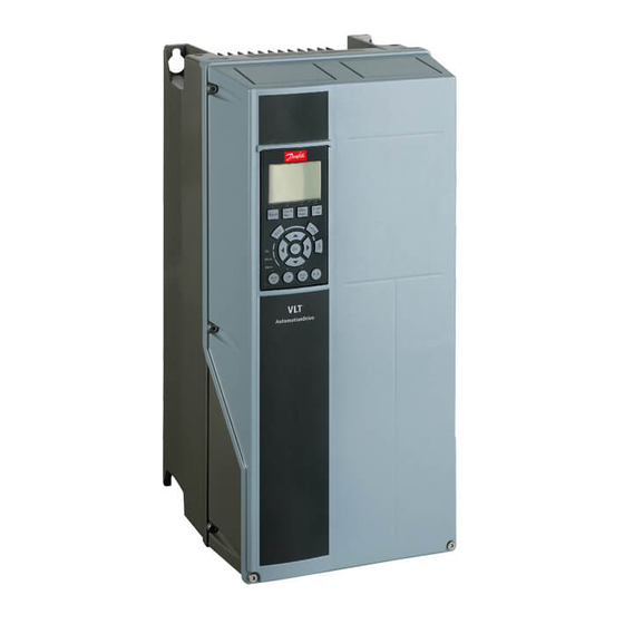
HVAC Drive FC 102, VLT
AutomationDrive FC 302 D4h-size VLT
mounted in a Rittal TS8 enclosure. The kit directs air in from
the bottom of the unit and out through the top of the unit.
See Illustration 1.1.
1
Back-channel airflow (exhaust)
2
Drive module
3
Back-channel airflow (intake)
4
Upper duct assembly
5
Lower duct assembly
Illustration 1.1 Direction of Airflow with the Kit Installed
Kit Part Number
Part number
176F6491
Table 1.1 Part Number for the VLT
In-bottom/Out-top Cooling Kit
®
AQUA Drive FC 202, and VLT
®
Parallel Drive Modules
Kit description
In-bottom/Out-top Cooling Kit for
®
the VLT
Parallel Drive Modules
(2-drive system)
®
Parallel Drive Modules
Danfoss A/S © 04/2016 All rights reserved.
Items Supplied
Enclosure mounting assembly
®
•
Base mounting plate, 38 mm (1.5 in.) (4)
•
Gasket, base mounting plate (4)
•
Slot gasket between drive module and mounting
backplate (2)
•
M5 nuts (20)
•
Screws, M5x16 (14)
Upper duct assembly
1
Gasket between grill and top cover panel (1)
2
Grill (1)
3
Gasket, top front cover (1)
4
Gasket, left front cover (1)
5
Gasket, bottom front cover (1)
6
Front cover plate (1)
7
Gasket between duct enclosure and grill (1)
8
Duct enclosure (1)
9
Gasket, right front cover (1)
10
Gasket between duct enclosure and base plate (1)
11
Base plate (1)
12
Gasket between base plate and module (1)
–
Nuts, M5 (26)
–
Screws, M5x12 (6)
Illustration 1.2 Upper Duct Assembly for 1 Drive Module
MI92M102
Advertisement

Summary of Contents for Danfoss 176F6491
- Page 1 Parallel Drive Modules – Screws, M5x12 (6) (2-drive system) ® Table 1.1 Part Number for the VLT Parallel Drive Modules Illustration 1.2 Upper Duct Assembly for 1 Drive Module In-bottom/Out-top Cooling Kit Danfoss A/S © 04/2016 All rights reserved. MI92M102...
-
Page 2: Discharge Time
Gasket, lower strip on front side of duct enclosure (1) followed, meet specific agency approvals and certifications. Gasket between top plate and lower duct enclosure (1) Seek agency approvals or certifications apart from Danfoss if Top side plate (2) designing and building other configurations. - Page 3 Secure each access plate with 8 M5 nuts and torque to 5.1 N · m (45 in-lb). Apply gaskets (12) to each side rail on the duct enclosure. Install the front plate (7) and secure with 11 M5 nuts. Torque to 5.1 N · m (45 in-lb). MI92M102 Danfoss A/S © 04/2016 All rights reserved.
- Page 4 Gasket between grill and gland plate Gasket, lower strip on back side of duct Base cover plate U-shaped gasket Gasket between base cover plate and base plate Top side plate – – Danfoss A/S © 04/2016 All rights reserved. MI92M102...
- Page 5 Gasket, left front cover Gasket between duct enclosure and base plate Gasket, bottom front cover Base plate Front cover plate Gasket between base plate and module Illustration 1.5 Assembling the Upper Duct Assembly MI92M102 Danfoss A/S © 04/2016 All rights reserved.
- Page 6 Secure the duct assembly to the drive module with 6 M5x12 screws. Torque to 5.1 N · m (45 in-lb). Reinstall the DC fuses on top of the drive module. Install the next drive module to the mounting backplate. Danfoss A/S © 04/2016 All rights reserved. MI92M102...
- Page 7 Gasket between back exhaust and mounting backplate Upper mounting point for drive module (M10 pem nut) Slot gasket Mounting backplate – – Illustration 1.6 Installing the Drive Modules onto the Mounting Backplate MI92M102 Danfoss A/S © 04/2016 All rights reserved.
- Page 8 The openings must match to the exhaust vent Secure each base cover plate to the base plate using 12 M5 screws. Torque to 5.1 N · m (45 in-lb). Secure the back panel cover to the frame. Danfoss A/S © 04/2016 All rights reserved. MI92M102...
- Page 9 VLT® Series FC 102, FC 202, and FC 302 Illustration 1.9 Vent Opening Dimensions for the Base Plate M5 pem nut (24 total on base plate) Illustration 1.10 M5 Pem Nut Dimensions on the Base Plate MI92M102 Danfoss A/S © 04/2016 All rights reserved.
- Page 10 Danfoss can accept no responsibility for possible errors in catalogues, brochures and other printed material. Danfoss reserves the right to alter its products without notice. This also applies to products already on order provided that such alterations can be made without subsequential changes being necessary in specifications already agreed. All trademarks in this material are property of the respective companies. Danfoss and the Danfoss logotype are trademarks of Danfoss A/S.


Need help?
Do you have a question about the 176F6491 and is the answer not in the manual?
Questions and answers