Advertisement
WF200 - Wood Fired Boiler
INSTALLATION AND OPERATION MANUAL
Version Date: 2018-05-07
SAVE THESE INSTRUCTIONS
TABLE OF CONTENTS
1.0
INTRODUCTION ................................................................................................................ 2
2.0
SPECIFICATIONS .............................................................................................................. 3
3.0
BOILER LOCATION .......................................................................................................... 4
4.0
VENTING FLUE GASES .................................................................................................... 6
5.0
BOILER SYSTEM PIPING & CONTROL WIRING ......................................................... 8
6.0
AIR DAMPER CONTROL & OPERATION .................................................................... 16
7.0
INSTALLATION & OPERATION CHECKLIST............................................................. 17
8.0
ANNUAL MAINTENANCE AND INSPECTION ........................................................... 19
HAZARD SYMBOLS AND DEFINITIONS
Danger Sign: Indicates a hazardous situation which, if not avoided, will
result in serious injury or death.
Warning Sign: Indicates a hazardous situation which, if not avoided,
could result in serious injury or death.
Caution Sign plus Safety Alert Symbol: Indicates a hazardous situation
which, if not avoided, could result in minor or moderate injury.
Caution Sign without Safety Alert Symbol: Indicates a hazardous
situation which, if not avoided, could result in property damage.
Notice Sign: Indicates a hazardous situation which, if not avoided,
could result in property damage.
unit may result in property damage, serious injury to occupants, or possibly death.
This Boiler must be installed by a licensed and trained Heating
Technician or the Warranty is Void. Failure to properly install this
30 Stonegate Dr.,
Saint John, NB,
E2H 0A4
Visit us
online
NTI # 86241
Advertisement

Subscribe to Our Youtube Channel
Related Manuals for NTI WF200


Summary of Contents for NTI WF200
-
Page 1: Table Of Contents
WF200 – Wood Fired Boiler INSTALLATION AND OPERATION MANUAL Version Date: 2018-05-07 30 Stonegate Dr., SAVE THESE INSTRUCTIONS Saint John, NB, E2H 0A4 TABLE OF CONTENTS INTRODUCTION ........................ 2 SPECIFICATIONS ......................3 BOILER LOCATION ......................4 VENTING FLUE GASES ....................6 BOILER SYSTEM PIPING &... -
Page 2: Introduction
WF200 1.0 INTRODUCTION Read Before Proceeding The installation of your NTI Wood Fired boiler must conform to the requirements of this manual, your local authority, and the latest edition of CSA standard B365 Installation code for solid-fuel-burning appliances and equipment. -
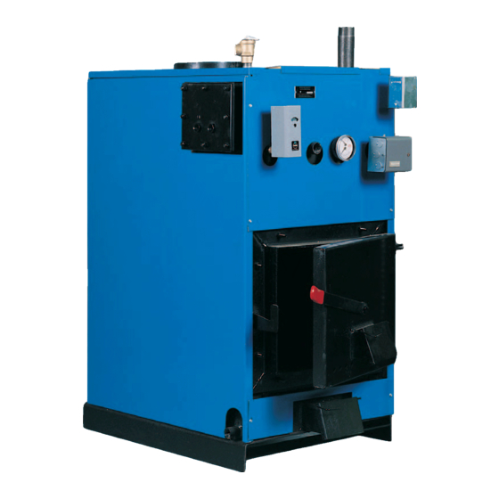
Page 3: Specifications
WF200 Installation and Operation Manual 2.0 SPECIFICATIONS Parts Diagram Flush Jacket Tapping provided for Domestic Coil ¾” Low water cut-off Normally Open Zone Valve Model OEM 170 V8043D1 Safeguard Relief Valve Tapping Or Approved Equal Flue Relief Valve Tapping Supply Tapping... -
Page 4: Boiler Location
WF200 3.0 BOILER LOCATION In all cases, the WF200 boiler must be installed indoors in a dry location where the ambient temperature must be maintained above freezing and below 100F [38C]. All boiler components must be protected from dripping, spraying water, or rain during operation and servicing. Consider the proximity of system piping, electrical supply and chimney termination when determining the best boiler location. - Page 5 WF200 Installation and Operation Manual Table 3-1 Minimum Clearances for Installation and Service Dimensions Clearances Front Sides Rear Flue Pipe Minimum 48 in. 6 in. 6 in. 24 in. 18 in. Recommended 60 in. 36 in. 24 in. 36 in.
-
Page 6: Venting Flue Gases
Installation and Operation Manual WF200 VENTING FLUE GASES The WF200 Wood Fired boiler shall be safely vented to the outdoors in accordance with these instructions, CAN/CSA B365, Installation code for solid-fuel-burning appliances and equipment, and the National Building Code. Chimney Only a chimney meeting one of the criteria listed below (a or b) shall be used to vent the flue gases from the WF200 boiler. - Page 7 WF200 Installation and Operation Manual Figure 4-1 Venting Hookup For installations in the U.S., wood boilers require a barometric damper be installed in the Chimney Connector. Manual Draft Dampers – when installed, should provide no more than 80% closure when fully shut, and must also be installed on a short piece of flue pipe that is easily removed to facilitate cleaning.
-
Page 8: Boiler System Piping & Control Wiring
Installation and set-up of the Boiler System Piping and Control Wiring for the WF200 will depend largely on the application it is being used in. This section of the manual details the two basic types of applications:... - Page 9 15 PSI at the boiler outlet. Pressure Relief Valve – A Pressure Relief Valve is factory supplied with each unit. WF200 boilers have a maximum allowable operating pressure of 30 PSI. The pressure relief valve must be installed at the top of the boiler (see Figures 5-1 &...
- Page 10 (or Dump Zone) designed to dissipate at least 10% of the Approximate Firing Rate of the WF200 in the event that circulation is reduced because of electrical power failure; see Figures 5-1 through 5-4. It is recommended to position the dump zone above the boiler, and to design to loop to promote natural thermal circulation.
- Page 11 WF200 Installed as an Add-on to an Oil Boiler The WF200 is factory supplied with controls necessary for a typical installation as an add-on to oil boiler. In addition to the preceding General Field Wiring and the General Boiler System Plumbing instructions, use the follow instructions to complete the plumbing and wiring for a WF200 installed as an add-on to an oil boiler.
- Page 12 Installation and Operation Manual WF200 Figure 5-2 WF200 Installed as an Add-on to an Oil Boiler – Wiring Diagram Dump Zone Valve Transformer 120/24VAC System Pump Transformer 120/24VAC Oil Burner Damper Motor Wood Boiler Pump NTI P/N Model Operation SPST switch makes on temp. Rise to set point. Breaks on fall from set point minus differential.
- Page 13 WF200 Installation and Operation Manual Control Sequence for Oil Add-on: 1. Standby ( T T Open, No Wood Fire ) – Oil boiler operates as normal. 2. Standby ( T T Open, Wood Fire) – When the temperature in wood boiler rises to the set point of the L4006B control, the wood circulator is energized (pumping wood boiler water into the existing oil boiler), and power is energized to the switching relay Pn.
- Page 14 WF200 Installed as Stand-alone Boiler The WF200 is factory supplied with controls necessary for a typical installation as an add-on to oil boiler; when installed as a stand-alone, the installer must supply a high limit Triple Aquastat (e.g. L8124A) to operate the damper motor and circulator.
- Page 15 WF200 Installation and Operation Manual Suggested Control Settings for Stand-alone Application: Wood boiler Aquastat (e.g. L8124A) – HI 200º, LOW 180º, Diff 10º Wood boiler high limit (L4081A) – HI 220º, LOW NA Control Sequence for Stand-alone Application: 1.
-
Page 16: Air Damper Control & Operation
AIR DAMPER CONTROL & OPERATION The WF200 is equipped with two air dampers, one located on the fire chamber access door, the second directly below. Both dampers are to be operated by a single damper motor via factory supplied chain; see Figure 6-1. -
Page 17: Installation & Operation Checklist
8. Do not load wood above the water baffle. 9. Do not adjust draft higher than 0.5 in. H 10. Never mechanically force air into the combustion chamber – the WF200 is suitable for natural draft only – boiler is not suitable for Stoker firing. - Page 18 Installation and Operation Manual WF200 Creosote Formation – When combustion is not complete or when the wood doesn’t burn completely, unburned gases are given off. These unburned gases will be drawn through the boiler into the smoke pipe and exhausted through the chimney; when these gases cool down, creosote results. The colder the gases get the harder the creosote forms;...
-
Page 19: Annual Maintenance And Inspection
Installation and Operation Manual ANNUAL MAINTENANCE AND INSPECTION The WF200 must be inspected and serviced regularly throughout the heating season by the operator as per Operation Checklist in Section 7.0; in addition, the boiler must be inspected and serviced annually by a Qualified Technician. - Page 20 Installation and Operation Manual WF200 Visit us online NY Thermal Inc. 30 Stonegate Dr. Saint John, NB E2H 0A4 Canada Technical Assistance: 1-800-688-2575 Website: www.ntiboilers.com Fax: 1-506-432-1135...
Need help?
Do you have a question about the WF200 and is the answer not in the manual?
Questions and answers