Table of Contents
Advertisement
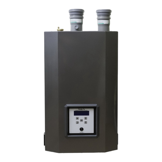
Trinity Tx
Model Numbers: Tx 51 - 200
Version Date: 2014-08-28
INSTALLATION AND OPERATION
INSTRUCTIONS FOR TRINITY Tx BOILER
TABLE OF CONTENTS
1.0
Introduction ................................................................................................................ 3
2.0
Specifications .............................................................................................................. 6
3.0
Boiler Location .......................................................................................................... 7
4.0
General Venting ....................................................................................................... 10
5.0
Vent/Air-Inlet Termination Clearances ..................................................... 24
6.0
Condensate Drain .................................................................................................... 27
7.0
Installing Gas Piping .............................................................................................. 29
8.0
Lighting The Boiler ................................................................................................. 31
9.0
Gas Valve And Burner Set-Up ............................................................................ 34
10.0 BOILER AND HEATING SYSTEM PIPING ................................................................... 37
11.0 DOMESTIC HOT WATER (DHW) PIPING – TX151C & TX200C (COMBI) ............... 48
12.0 FIELD WIRING ................................................................................................................. 52
13.0 CASCADE INSTRUCTIONS ............................................................................................ 55
14.0 WIRING SCHEMATICS ................................................................................................... 57
15.0 INSTALLATION CHECKLIST ........................................................................................ 59
16.0 ANNUAL MAINTENANCE AND INSPECTION ........................................................... 60
17.0 DISPLAY MENU GUIDE ................................................................................................. 62
18.0 TROUBLESHOOTING ..................................................................................................... 74
19.0 PARTS LIST ...................................................................................................................... 77
HAZARD SYMBOLS AND DEFINITIONS
unit may result in property damage, serious injury to occupants, or possibly death.
NEW PRODUCT LINE
High Efficiency
Condensing Gas Boiler
Danger Sign: Indicates a hazardous situation which, if not avoided, will
result in serious injury or death.
Warning Sign: Indicates a hazardous situation which, if not avoided,
could result in serious injury or death.
Caution Sign plus Safety Alert Symbol: Indicates a hazardous situation
which, if not avoided, could result in minor or moderate injury.
Caution Sign without Safety Alert Symbol: Indicates a hazardous
situation which, if not avoided, could result in property damage.
Notice Sign: Indicates a hazardous situation which, if not avoided,
could result in property damage.
This Boiler must be installed by a licensed and trained Heating
Technician or the Warranty is Void. Failure to properly install this
H
NTI # 84874
Advertisement
Table of Contents


Need help?
Do you have a question about the Trinity TX51 and is the answer not in the manual?
Questions and answers