Table of Contents
Advertisement
Quick Links
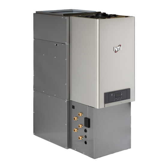
GF150 Installation Manual
Combination gas-fired, condensing
combi boiler and space heating fan coil
C
NSF/ANSI 372
Keep this manual near this appliance for future reference
whenever maintenance or service is required.
WARNING
This appliance (GF150) is a combination gas-fired, condensing, combi boiler and space heating
fan coil. The boiler is a CSA-certified product in its own right and, as such, must be installed
according to its installation and operation manuals (supplied).
This manual provides installation instructions for the GF150, but defers to the boiler's manual(s)
where appropriate. Throughout, in any conflict between instructions from this manual and those
from the boiler's, the latter are assumed to be correct (unless otherwise noted). When reading
the boiler manuals, only sections pertaining to the TRX150C model may apply.
If the information in these instructions is not followed exactly, a fire or explosion may result,
causing property damage, personal injury or death.
Do not store or use gasoline or other flammable vapors and liquids in the vicinity of this or any
other appliance.
What to do if you smell gas
Do not try to light any appliance.
●
Do not touch any electrical switch; do not use any phone in your building.
●
Immediately call your gas supplier from a neighbor's phone. Follow the gas supplier's instructions.
●
If you cannot reach your gas supplier, call the fire department.
●
Installation and service must be performed by a qualified installer, service agency or the gas supplier.
The installation must conform with local codes or, in the absence of local codes, the National Fuel
Gas Code, ANSIZ223.1/NFPA 54 and/or CSA B149.1, Natural Gas and Propane Installation Code.
When applicable, the installation must conform with the Manufactured Home Construction and
Safety Standard, Title 24 CFR, Part 3280 and/or CAN/CSA Z240 MH Series, Mobile Homes.
®
US
2
1
A
B
C
Modification description
Designer
Revision
Document code
Precision level for dimentions without tolerance indications has to be:
F
M
C
V
EN 22768-ISO 2768
H
K
L
= 0
= 0
= 0
D
Material
Conformity requirements see the document named "R&D.TB005Tt-xx"
Treatment
XX
Finishing
Production Plant
Description
30 Stonegate Drive,
Saint John, NB E2H 0A4
BY TERM LAWS WE RESERVE THE PROPERTY OF THIS DRAWING WITH PROHIBITION OF USE AND REPRODUCTION
1
2
3
4
A
B
C
Date
Code
RL
ECN first creation
xx.xx.20xx
Date
D. Grimmer
Designer
Drawing format
A4
Scale
1:1
D
Code
3
4
Advertisement
Table of Contents

Related Manuals for NTI GF150


Summary of Contents for NTI GF150
- Page 1 BY TERM LAWS WE RESERVE THE PROPERTY OF THIS DRAWING WITH PROHIBITION OF USE AND REPRODUCTION according to its installation and operation manuals (supplied). This manual provides installation instructions for the GF150, but defers to the boiler’s manual(s) where appropriate. Throughout, in any conflict between instructions from this manual and those from the boiler’s, the latter are assumed to be correct (unless otherwise noted).
-
Page 2: Table Of Contents
Contents 1. Important Information 1.1 Safety Information 2. About the Appliance 2.1 Items Included 2.2 Specifications 2.3 Display 2.4 Components 2.5 Dimensions 2.6 Rating Plate 3. Installing the Appliance 3.1 Choosing an Installation Location 3.2 Installation Clearances 3.3 Ducting the Appliance 3.4 Connecting the Condensate Drain 3.5 Connecting the Water Piping 3.6 Connecting a CH System... -
Page 3: Important Information
(supplied). This manual provides installation instructions for DANGER the GF150, but defers to the boiler manuals where appropriate. Throughout, in any conflict between instructions from this manual and those from the boiler’s, the latter are assumed to be correct. - Page 4 WARNING CAUTION Do not turn on the appliance unless the water and ● gas supplies are fully opened. Doing so may damage the appliance. Do not turn on the water if the cold water supply ● shut-off valve is closed. Doing so may damage the appliance.
-
Page 5: About The Appliance
When you open the packaging, you will find the following items with the appliance. Check for each of the following items before installing the appliance. The manual packet and kit box can be found inside the front cover. GF150 Installation Manual TRX150C Manuals and other Documentation Kit Box, including: Item Part No. -
Page 6: Specifications
Flame Rectifier Probe, Temperature Limit Control (190°F), Water Pressure Switch (min. 8 PSI), Freeze Protection, Blocked Condensate Pressure Switch, Condensate Trap, Safety Devices Flue Temperature High Limit Sensor (210°F), Blocked Vent Pressure Switch, Coil Freeze Protection (Plenum Sensor; Fan RPM Sensor) *The TRX150C is the boiler component of the GF150. -
Page 7: Display
2.3 Display (HMI) AUTO COMFORT 7 8 9 ON OFF MENU PAR CODE ON / OFF Button (see NOTICE below) Digits Indicating: Domestic Hot Water Adjustment Button +/- • Boiler Status MENU: (short press = User Menu); ° • Temperature ( F) with bar level (long press = Info Menu) •... -
Page 8: Components
2.4 Components The following diagram shows the key components of the appliance. A more detailed drawing of the boiler itself is included in its manual. Component assembly diagrams and particular parts lists are included in the Appendixes. Exhaust Duct PRV (Pressure Relief Valve), 30 psi APS (Air Pressure Sensor) Manual Purge Valve Ignition Transformer... -
Page 9: Dimensions
2.5 Dimensions The following diagrams show the dimensions of the appliance and the connections. 20.56 7.85 16.66 1.05 35.69 17.86 23.85 2.50 DHW outlet CH supply Gas inlet CH return DHW inlet 5.75 2.00 typ. Rear Left Side... -
Page 10: Rating Plate
Fabriques au Canada COMBINATION GAS COMBI BOILER / CENTRAL AIR HEATING COMBINAISON CHAUDIÈRE COMBI / CHAUFFAGE DE L'ESPACE 2105262138174672 Serial No. NTI Boilers Inc. 30 Stonegate Drive Saint John, NB E2H 0A4 Input, MBH Heating Capacity, MBH [Entrée, kW] [Capacité de chauffage, kW]... -
Page 11: Installing The Appliance
3. Installing the appliance Adequate drainage Maintain proper clearances from any openings in ● NTI recommends that the connections be made in the building. the following order to ensure ease of installation, Install the appliance with a minimum clearance given the limited space in the piping cabinet: ●... -
Page 12: Installation Clearances
As a space-saving measure, the top 10" of cabinet may be removed (6 screws on the inside flanges) to 9 in as required reduce the overall height of the GF150 + A/C unit. Back Front 0 | 24 in* REMOVABLE... - Page 13 Bottom return: RACK A removable panel is included as part of the floor of the GF150. To remove it, simply remove the 4 screws a) Side return: from the panel’s front flange, and rotate the panel about its rear flange to release it.
-
Page 14: Connecting The Condensate Drain
3.4 Connecting the Condensate Drain Do not reduce the size of the condensate line. The line must at minimum equal the diameter of the line included with the appliance. CAUTION A frozen condensate line could result in a blocked This condensing high efficiency appliance has a vent condition. - Page 15 WARNING CONDENSATE PIPING (SUGGESTED SETUP FOR THE CONDENSATE TRAP MUST BE FILLED WITH CONDENSATE REMOVAL WATER BEFORE THE BOILER IS USED. TO FLOOR DRAIN) The siphon is filled with water during the air purging procedure. See Filling Procedure in this manual for further instructions.
-
Page 16: Connecting The Water Piping
3.5.3 Expansion Tank The control module uses temperature ● sensors to provide both high limit protection An expansion tank is provided with the GF150 for and modulating temperature control. The standalone installations (without external hydronic control module may also provide low water loads). - Page 17 3.5.4 CH and DHW Pressure Relief Valves CH Loop This appliance is provided with a CH PRV that complies with the ANSI/ASME Boiler and Pressure WARNING Vessel Code, Section IV (Heating Boilers). The To avoid water damage or scalding due to relief valve included 30 psi CH PRV must be installed at the top operation: of the boiler, using the included pipe adapter and...
- Page 18 BTU/H input capacity of the boiler. Installing the DHW PRV Left configuration Right configuration 1. The GF150 is factory-configured with all water, gas, and condensate connections on the left. When swapping DHW Inlet and Outlet The CH connections are fixed to the left side,...
- Page 19 3.5.5 Example plumbing layout All field DHW, CH, and Gas fittings are 3/4" NPT-M. Example shown here without external CH loop (fittings capped off at factory). EXPANSION TANK PRESSURE (to fixtures) RELIEF VALVE (30 psi) COLD SUPPLY SHUT OFF VALVES (to drain) DRAINS (typ.) PRESSURE...
- Page 20 5. The water entering the boiler circuit should activate PURGE mode, which will engage the pump to clear the air from the heating coil. The GF150 is factory-configured with a manual filling valve to allow the appliance to be filled •...
-
Page 21: Connecting A Ch System
While the general information regarding PRVs Filling Valve ● Return from Space remains accurate, the maximum pressure rating for Heating Fan Coil Supply the GF150 is 125 PSI. Do NOT install a 150 PSI PRV. 3-way Valve Return GF150 with Multiple Central Heating Circulators:... - Page 22 GF150 with Single Central Heating Circulator: GF150 without Central Heating Circulator:...
- Page 23 Head, ft Flow, USGPM K. Load balancing While the GF150 is able to supply both its internal forced-air coil and an external hydronic load simul- taneously, the internal piping (and pump) are still subject proprotional flow.
-
Page 24: Venting The Appliance
Before connecting the gas supply, determine ● the gas type and pressure for the appliance The GF150 is heated by a TRX150C combi boiler, by referring to the rating plate. Use only itself a CSA-certified heating appliance. the same gas type indicated on the rating plate. - Page 25 4. Determine the proper size and type for the gas in the boiler installation manual (supplied). line (use Local or National Gas Codes). The GF150 is heated by a TRX150C combi boiler, 5. Install full port valves on the gas supply line and itself a CSA-certified heating appliance.
-
Page 26: Connecting The Electrical
3.9 Connecting the Electrical A 7/8" (0.875 in.) panel hole is provided on each side of the cabinet for mechanical strain relief of WARNING the power supply wiring (see "Line Voltage" in the following diagram): Improperly connecting the power supply can result in electrical shock and electrocution. - Page 27 3.9.1 Connecting the line voltage wiring Freeze protection: The GF150 protects its heating coil from freezing When connecting the power supply wires to the by only allowing the A/C system's condenser Field Wiring Panel, use positions 1, 3, and 5 for Line,...
-
Page 28: Configuring The Appliance
The various modes above affect how the target their respective ranges. set point is calculated, but the GF150 allows the installer to dictate the Maximum [ 4.2.5 ] and For example, using the factory default values: Minimum [ 4.2.6 ] set points the boiler will supply to... - Page 29 This chart shows how adjusting the Max. and Mix. blower rate values can affect the resulting flow rate for a given set point (and set point range). 1400 1200 1000 400-800 500-1000 800-1200 4.2.6: 4.2.5: 115°F 160°F Set point (°F) Set Point (F) This table shows approximate heat output and supply air temperatures for a given combination of water temperatures and air flow rates.
- Page 30 Maximum Blower Rate (CFM) Firmware v1.10.03 Firmware v1.10.03 These tables apply to firmware Note versions 1.10.03 and later (May 2022). For earlier versions, please call NTI Technical Support.
- Page 31 Maximum Blower Rate (CFM) 1000 1100 1200...
- Page 32 420 CFM, which Cooling and Ventilation Mode would appear as on the red LED display: The GF150 is compatible with up to 3 tons of Flow Rate: 420 CFM cooling (or heat pump) capacity.
- Page 33 Blower-off Delay 30 s 60 s 90 s 3.10.4 Blower Parameters – Cooling and Ventilation Modes Cooling (Y1/Y2) Cooling Adjustment Adjustment (%) 1.5 ton 2 ton 2.5 ton 3 ton + 7.5% Normal - 7.5% - 15% CFM (@ Y2) 1000 1200 1.5 ton...
- Page 34 NOTES...
- Page 35 NOTES...
- Page 36 NOTES...
-
Page 37: Appendices
4. Appendices 4.1 Blower Performance GF150 — Blower performance 1600 1400 Isobars : 1200 Torque Max. = 0.8 in. w.c. 1000 0.50 in. w.c. 0.25 in. w.c. 0.1 in. w.c. 1000 1200 1400 1600... -
Page 38: Wiring Diagram
4.2 Wiring Diagram... -
Page 39: Ladder Diagram
4.3 Ladder Diagram... -
Page 40: Component Diagrams And Parts Lists
4.4 Component Diagrams and Parts Lists... -
Page 42: Installation Checklist
Have you completed the Installation Checklist in the Boiler Installation Manual? The following check list is intended to supplement those found in the boiler manual, and focuses on installation details specific to the overall appliance (GF150). Connecting the Power Supply... -
Page 43: Troubleshooting
3-way Valve Error – valve not in correct Remove all thermostat demands position after start-up/'home' position call Reboot GF150 PCB (disconnect 24 V AC power via 2-pole connector on top-left -- yellow wires from transformer) The 3WV should start humming on power-up, cycling through its 'Home' position (which should clear the error) and ending in the Forced AIr Heating position. - Page 44 Installation Manual GF150 Getting Service If your appliance requires service, you have several options for getting service: Contact Technical Support at 1-800-688-2575 or on the website: www.NTIBoilers.com. ● For warranty service, always contact Technical Support first. ● Contact the technician or professional who installed your boiler.
Need help?
Do you have a question about the GF150 and is the answer not in the manual?
Questions and answers