Table of Contents
Advertisement
Installation
Start-Up
Maintenance
Parts
Warranty
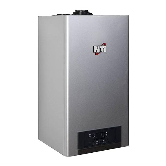
Residential Condensing Gas Boiler
Heat Exchanger Bears the ASME "H" Stamp
DANGER
THIS MANUAL MUST ONLY BE USED BY A QUALIFIED INSTALLER /
SERVICE TECHNICIAN. READ ALL INSTRUCTIONS IN THIS MANUAL
BEFORE INSTALLING. PERFORM STEPS IN THE GIVEN ORDER. FAILURE
TO DO SO COULD RESULT IN SUBSTANTIAL PROPERTY DAMAGE, SEVERE
PERSONAL INJURY, OR DEATH.
WARNING
Improper installation, adjustment, alteration, service, or maintenance
could void product warranty and cause property damage, severe
personal injury, or death.
California Proposition 65 Warning: This product contains chemicals
known to the State of California to cause cancer, birth defects, or
other reproductive harm.
NOTICE
The manufacturer reserves the right to make product changes or updates
without notice and will not be held liable for typographical errors in literature.
The surfaces of these products contacted by potable (consumable) water
contain less than 0.25% lead by weight as required by the Safe Drinking Water
Act, Section 1417.
TRX
TRX
Advertisement
Table of Contents
Troubleshooting

Related Manuals for NTI TRX Series


Summary of Contents for NTI TRX Series
- Page 1 Installation Start-Up Maintenance Residential Condensing Gas Boiler Parts Warranty Heat Exchanger Bears the ASME “H” Stamp DANGER THIS MANUAL MUST ONLY BE USED BY A QUALIFIED INSTALLER / SERVICE TECHNICIAN. READ ALL INSTRUCTIONS IN THIS MANUAL BEFORE INSTALLING. PERFORM STEPS IN THE GIVEN ORDER. FAILURE TO DO SO COULD RESULT IN SUBSTANTIAL PROPERTY DAMAGE, SEVERE PERSONAL INJURY, OR DEATH.
- Page 2 WARNING WARNING: If the information in these instructions is not followed exactly, a fire or explosion may result causing property damage, personal injury or death. • Do not store or use gasoline or other flammable vapors and liquids in the vicinity of this or any other appliance. WHAT TO DO IF YOU SMELL GAS •...
- Page 3 SPECIAL ATTENTION BOXES Installation should be made in accordance with the regulations of the Authority Having Jurisdiction, local code authorities, and utility The following defined terms are used throughout this companies which pertain to this type of water heating equipment. manual to bring attention to the presence of hazards of Authority Having Jurisdiction (AHJ) –...
- Page 4 In accordance with Section 325 (f) (3) of the Energy Policy and work to shutoff the fuel supply when the system water temperature Conservation Act, NTI has provided this boiler with multiple reaches the preset operating temperature; and they cause a safety...
-
Page 5: Table Of Contents
J. Outdoor Heating Curve Parallel Shift D. Wall Mounting Considerations K. Room temperature Day /Night E. Wall Mounting Instructions (Only applicable when using NTI room sensor) 1. Mounting to a Wood Studded Wall L. Time programs – heating schedule 2. Mounting to a Metal Frame (Only applicable when using NTI room sensor) F. -
Page 6: Part 1 - General Safety Information
Part 1 - General Safety Information This boiler is approved for indoor installations only and is not intended WARNING for use as a pool heater. Clearance to combustible materials: 0” top, bottom, sides, and back. Boiler must have room for service: 18” front, This boiler must be installed by a qualified service technician. -
Page 7: Improper Combustion
DO NOT alter or modify the appliance or appliance controls. WARNING Altering any NTI boiler with parts not manufactured by NTI WILL INSTANTLY VOID the boiler warranty and could result in property Be sure to disconnect electrical power before opening boiler damage, personal injury, or death. -
Page 8: Ch And Dhw Loop Water Chemistry Requirements
Potable water is defined as drinkable CH applications. water supplied from utility or well water in compliance with EPA NOTE: NTI DOES NOT WARRANT THE BOILER AGAINST FREEZE-RELATED secondary maximum contaminant levels (40 CFR Part 143.3). If DAMAGE. -
Page 9: Water Temperature Adjustment And Scalding
Part 1 - General Safety Information CAUTION I. High Elevation Installations WARNING On TRX085 / TRX120 Models ONLY If the boiler to be used only in Heating Mode (not connected to an indirect water heater), the electrical connection of Natural gas at high elevation might contain less heating value than the 3-way valve motor MUST BE DISCONNECTED while typical 1,000 BTU/cu ft and therefore can cause improper air / gas the boiler is operating in central heating mode. -
Page 10: Part 2 - Before You Start
• Immediately call your gas supplier from a neighbor’s phone. Follow the gas supplier’s instructions. THIS MANUAL MUST ONLY BE USED BY A QUALIFIED INSTALLER / TRX series • If you cannot reach your gas supplier, call the fire department. SERVICE TECHNICIAN. READ ALL INSTRUCTIONS IN THIS MANUAL Installation and service must be provided by a qualified installer, BEFORE INSTALLING. - Page 11 Part 2 - Before You Start How the Boiler Operates TRX150C / TRX120 TRX condensing technology intelligently delivers hydronic heating while maximizing efficiency. Outlined below are system features and operation: Stainless Steel Heat Exchanger The highly efficient stainless steel heat exchanger is designed to extract all available heat from the supply line before it is exhausted.
-
Page 12: Optional Equipment
Protects the boiler from damage in low flow conditions. Internal ECM Pump The internal ECM Pump uses less electricity than standard pumps, providing high performance operation. B. Optional Equipment Optional equipment available from NTI (and Part #): • System Sensor (84010) • 3” PVC Concentric Vent Kit (84634) •... -
Page 13: Part 3 - Prepare The Boiler For Installation
Part 3 - Prepare the Boiler for Installation CAUTION CAUTION The service life of the boiler’s exposed metallic surfaces, such COLD WEATHER HANDLING - If the boiler has been stored in as the casing, as well as internal surfaces, such as the heat a very cold location (BELOW 0 F) before installation, handle with exchanger, are directly influenced by proximity to damp and salty... -
Page 14: Leveling
Part 3 - Prepare the Boiler for Installation NOTE: For closet installations, a combustible door or removable NOTE: When installing in a zero clearance location, it may not be panel is acceptable front clearance. A 3” minimum clearance must be possible to read or view some product labeling. -
Page 15: Wall Mounting Instructions
Part 3 - Prepare the Boiler for Installation 2. Mounting to a Wood Studded Wall WARNING CAUTION Do not mount the boiler to a hollow wall. If the boiler is not installed upright, vertically plumb, and level, improper and unsatisfactory operation may occur, causing excessive E. -
Page 16: Residential Garage And Closet Installations
Part 3 - Prepare the Boiler for Installation F. Residential Garage and Closet Installations CAUTION Check with your local Authority Having Jurisdiction for requirements when installing boiler in a garage or closet. Please read the entire ” manual before attempting installation. Failure to properly take 6 ,4 (4 0 factors such as boiler venting, piping, condensate removal, and... -
Page 17: Power Venting, Indoor Combustion Air In Confined Or Unconfined
Part 3 - Prepare the Boiler for Installation Venting. installed on each additional level of the dwelling, building, or structure Be sure to locate the boiler such that the exhaust vent and intake served by the vented gas appliance. It shall be the responsibility of the piping can be routed through the building and properly terminated. -
Page 18: Removing A Boiler From A Common Vent System
Part 3 - Prepare the Boiler for Installation Figure 9 - CO Warning Label J. Removing a Boiler from a Common Vent System DANGER Do not install the boiler into a common vent with any other appliance. This will cause flue gas spillage or appliance malfunction, resulting in possible substantial property damage, severe personal injury, or death. -
Page 19: Technical Specifications
Part 3 - Prepare the Boiler for Installation K. Technical Specifications Model TRX085 TRX120 TRX110C TRX150C Type Boiler Combi Installation Indoor, Wall Hung, Fully Condensing Space Heating 9,400 / 85,000 13,200 / 120,000 11,200 / 106,000 13,200 / 120,000 Minimum / Maximum Input (Btu/Hr) Domestic Hot Water 11,200 / 114,000 13,200 / 150,000... - Page 20 Part 3 - Prepare the Boiler for Installation 4-3/4” 4-3/4” (120 mm) (120 mm) 15-3/4” (400 mm) 2-9/16” 2-5/8” 2-5/8” 2-9/16” (65mm) (67mm) (67mm) (65mm) 2-3/16” 3-7/16” 3-7/16” 3-7/16” 3-7/16” (55,3mm) 5-7/8” (87,2 mm) (87,6 mm) (87,6 mm) (87,2 mm) (150 mm) 15-5/16”...
- Page 21 Part 3 - Prepare the Boiler for Installation TRX085 - TRX120 Pressure relief valve Circulation Pump with auto air vent Air purge valve Water pressure switch Boiler outlet temperature sensor Modulating Fan Air pressure switch Boiler inlet temperature sensor Flue gas temperature sensor Frame Main heat exchanger Ignition electrode...
- Page 22 Part 3 - Prepare the Boiler for Installation TRX110C - TRX150C Pressure relief valve CH circuit filter Air purge valve Circulation Pump with auto air vent Boiler outlet temperature sensor DHW Flow switch Air pressure switch Water pressure switch Flue gas temperature sensor Modulating Fan Main heat exchanger Boiler inlet temperature sensor...
- Page 23 Part 3 - Prepare the Boiler for Installation TRX085 - TRX120 TRX110C - TRX150C °F °F Pressure relief valve Air purge valve Boiler outlet temperature sensor Air pressure switch Flue gas temperature sensor Main heat exchanger Flame detection electrode Silencer Junction box DHW heat exchanger Condensate trap...
-
Page 24: Part 4 - Water Piping
NTI offers indirect water heaters in a wide range of gallon sizes in either Model Heat Exchanger Volume (Gallons) stainless steel or glass-lined construction. - Page 25 Connect the 3/4” DHW inlet and outlet pipes. A shut-off valve between the city water supply and DHW inlet is recommended for ease of service. NTI offers threaded 3/4” DHW tankless isolation valves with a DHW pressure relief valve for ease of installation and future service.
-
Page 26: Internal Circulation Pump
Part 4 - Water Piping E. Internal Circulation Pump F. By-Pass Valve This boiler has a by-pass valve which requires no adjustment. To calculate the size of the heating installation refer to the graph below. The by-pass valve protects the heat exchanger from overheating by Graph Representing the Available Circulation Pump Head guaranteeing a minimum flow rate of 2 gpm within the primary heat exchanger. -
Page 27: Ch And Dhw Pressure Relief Valves
Part 4 - Water Piping 4. Connect the pressure relief valve and gasket. G. CH and DHW Pressure Relief Valves An external pressure relief valve must be installed on this appliance for the NOTE: To maintain an airtight seal, ensure the gasket boot is CH loop. -
Page 28: Air Elimination Device
Part 4 - Water Piping WARNING WARNING Do not thread a cap or plug into the relief valve or relief valve line To avoid water damage or scalding due to relief valve operation: under any circumstances! Explosion and property damage, serious •... - Page 29 Part 4 - Water Piping Cap this fitting when not in Primary/Secondary Piping Shown Figure 22 - TRX085 / TRX120 with Single Central Heating Circulator NOTE: In piping applications utilizing a single zone, it is recommended NOTES: that the installer use flow / check valves with weighted seats at or near 1.
- Page 30 Part 4 - Water Piping Cap this fitting when not in Figure 23 - TRX085 / TRX120 without Central Heating Circulator NOTES: NOTE: In piping applications utilizing a single zone, it is recommended 1. This drawing is meant to show system piping concept only. that the installer use flow / check valves with weighted seats at or near Installer is responsible for all equipment and detailing required by the appliance to prevent gravity circulation.
- Page 31 Part 4 - Water Piping Cap this fitting when not in Primary/Secondary Piping is Required Figure 24 - TRX085 / TRX120 with Multiple Central Heating Circulators NOTES: NOTE: In piping applications utilizing a single zone, it is recommended 1. This drawing is meant to show system piping concept only. that the installer use flow / check valves with weighted seats at or near Installer is responsible for all equipment and detailing required by the appliance to prevent gravity circulation.
- Page 32 Part 4 - Water Piping Primary/Secondary Piping Shown Figure 25 - TRX110C / TRX150C with Single Central Heating Circulator NOTE: In piping applications utilizing a single zone, it is recommended NOTES: that the installer use flow / check valves with weighted seats at or near 1.
- Page 33 Part 4 - Water Piping Figure 26 - TRX110C / TRX150Cwithout Central Heating Circulator NOTES: NOTE: In piping applications utilizing a single zone, it is recommended This drawing is meant to show system piping concept only. that the installer use flow / check valves with weighted seats at or near Installer is responsible for all equipment and detailing required by the appliance to prevent gravity circulation.
- Page 34 Part 4 - Water Piping CAUTION Mixing valves are required for the protection of low temperature loops. Primary/Secondary Piping is Required Figure 27 - TRX110C / TRX150C with Multiple Central Heating Circulators NOTES: NOTE: In piping applications utilizing a single zone, it is recommended 1.
-
Page 35: Floor Drying Function
Part 4 - Water Piping H. Floor Drying Function The Floor Drying Function is a special function that allows the installer, through a dedicated heating cycle, to use the boiler for drying a freshly poured radiant floor during a floor system installation. The installer can set parameter 2.7.4 (Floor Drying Cycle) and choose the cycle‘s operation (Functional Heating, Curing Heating, a combination of Functional and Curing Heating, or Manual Heating). -
Page 36: Part 5 - Venting
Part 5 - Venting DANGER The boiler must be vented as detailed in this section. Ensure exhaust vent and intake piping complies with these instructions regarding vent system. Inspect finished exhaust vent and intake piping thoroughly to ensure all joints are well secured, airtight, and comply with all applicable code requirements, as well as the instructions provided in this manual. -
Page 37: Approved Materials For Exhaust Vent And Intake Pipe
Part 5 - Venting B. Approved Materials for Exhaust Vent and Intake Pipe Standards for Installation In: Item Material United States Canada Pipe and Fittings Approved for Intake ONLY ABS* ANSI/ASTM D2661 ANSI/ASTM D2661 PVC Schedule 40/80 ANSI/ASTM D1785 PVC-DWV Schedule 40/80 ANSI/ASTM D2665 PVC, CPVC, and PP Venting Must Pipe Approved for... -
Page 38: Exhaust Vent And Intake Pipe Location
Part 5 - Venting D. Exhaust Vent and Intake Pipe Location INSIDE CORNER DETAIL FIXED OPERABLE CLOSED FIXED CLOSED OPERABLE LP-179-CC 03/28/17 Exhaust Vent Terminal Intake Pipe Terminal Area Where Intake Terminal Is Not Permitted Figure 28 - Exit Terminals for Direct Vent Systems - ANSI Z223.1 / NFPA 54 for US and CAN/CSA B149.1 for Canada DESCRIPTION CANADA Clearance above grade, veranda, porch, deck, or balcony... -
Page 39: Exhaust Vent And Intake Pipe Sizing
Part 5 - Venting E. Exhaust Vent and Intake Pipe Sizing When preparing pipe for installation: 1. The factory ready exhaust vent and intake air pipe diameter is 2”. • Ensure cuts are square. The vent diameter can be increased to 3” by installing a reducing •... -
Page 40: Exhaust Vent And Intake Pipe Installation
Part 5 - Venting 2. If using the right side connection, remove the gear clamp from the G. Exhaust Vent and Intake Pipe Installation left side connection and install it on the right side. See Figure 32. WARNING WARNING All joints of positive pressure vent systems must be sealed completely You must cut out the plastic on the air intake connection being used to prevent leakage of flue products into the living space. - Page 41 Vent Option Availability Vent Supplier Vent Material Description Figure Size Part Number Compatibility Roof Wall 2” 196984 (NTI p/n 85062) 35, 39 IPEX Low Profile (Wall) 3” 196985 (NTI p/n 84357) 35, 39 2” 196125 36, 40, 45, 49 PVC/CPVC IPEX Concentric...
-
Page 42: Applications
Part 5 - Venting H. Applications 1. Direct Vent Installation of Exhaust and Intake If installing a direct vent option, combustion air must be drawn from the outdoors directly into the boiler intake, and exhaust must terminate outside. There are three basic direct vent options detailed in this manual: 1. - Page 43 Part 5 - Venting Sidewall Venting Options - Direct Vent Installation Low Profile Termination Two Pipe Termination WARNING WARNING Exhaust must terminate a minimum of 18” above the air intake Exhaust must terminate a minimum of 18” above the air intake termination.
- Page 44 Part 5 - Venting Sidewall Venting Options - Direct Vent Installation Low Profile Termination Two Pipe Termination WARNING 4 in min. Refer to documentation included with termination kit for complete installation instructions. Gas Vent Gas Vent Directly Directly Below Keep Free of Below Keep Obstructions Free of...
- Page 45 Part 5 - Venting Snorkel Venting (Two Pipe Sidewall Venting Terminations Beneath an Overhang) Figure 42 - Two Pipe Sidewall (Horizontal Snorkel) Venting NOTES: A. For every 1” of overhang, the exhaust vent must be located 1” vertical below the overhang (12” minimum). Overhang means top of building structure (roof ) and not two adjacent walls (corner of building).
- Page 46 Part 5 - Venting Roof Venting Options - Direct Vent Installation Unbalanced Termination (Roof Exhaust / Sidewall Intake) Two Pipe Termination WARNING WARNING Exhaust must terminate a minimum of 18” above the air intake Exhaust must terminate a minimum of 12” above snow level. See Figure termination.
- Page 47 Part 5 - Venting Roof Venting Options - Direct Vent Installation Unbalanced Venting - Roof Exhaust Termination Two Pipe Termination WARNING Figure illustrates two options for exhaust termination only. Neither vent pipe illustrated is intended for combustion air intake. 4 in min. Figure 47 - Two Pipe Roof Venting Detail Figure 48 - Unbalanced Venting - Roof Exhaust Termination Options Concentric Termination...
-
Page 48: Venting Through An Existing System
NOTE: The following instructions refer only to venting through an This boiler may be vented through an existing unused vent system. existing vent system, and not to venting with NTI’s optional concentric The inner diameter of the existing vent system is utilized for the vent kits. -
Page 49: Power Venting, Indoor Combustion Air In Confined Or Unconfined
Part 5 - Venting 3. Power Venting, Indoor Combustion Air in Confined or Unconfined Space This boiler requires fresh, uncontaminated air for safe operation and must be installed in a mechanical room where there is adequate combustion and ventilating air. NOTE: To prevent combustion air contamination, see Table 6. -
Page 50: Part 6 - Installing The Condensate Drain
If the boiler condensate outlet is lower than the drain, you must use a condensate removal pump (kit p/n 554200 available from NTI). NOTE: If a nearby laundry tub is used as a disposal for waste water from the washing machine, draining the condensate into this tub allows the soapy water discharge to neutralize the acidic condensate. -
Page 51: Part 7 - Connecting Electrical Service
Part 7 - Connecting Electrical Service WARNING Install wiring and electrically ground boiler in accordance with the authority having jurisdiction or, in the absence of such an authority, follow the National Electrical Code, NFPA 70, and/or CSA C22.1 Electrical PIPE HANGERS MUST CONDENSATE HOSE (supplied) BE USED TO SUPPORT... -
Page 52: Removing The Power Cord (To Hard Wire The Boiler)
Part 7 - Connecting Electrical Service Cut the cable inside the cabinet and below the plastic connector. NOTE: For additional electrical protection, the use of a whole house Remove the internal part of the cable from the junction box. surge protector is recommended. Damage caused by power surges IS Discard the internal and external parts of the cable. -
Page 53: Connecting Power (120V) For Dhw And Ch Circulators
Part 7 - Connecting Electrical Service 2. Connecting Power (120V) for DHW and CH Circulators To connect power for the CH and DHW external pump on the main PCB: Shut off the power supply at the boiler and at the circuit breaker. Shut off the gas at the manual shutoff. -
Page 54: Room Thermostat Wiring Connections
Part 7 - Connecting Electrical Service 4. Room Thermostat Wiring Connections To connect a room thermostat: 1. Access the low voltage wiring connections by following the directions in Item 3, Low Voltage Wiring Connections. 2. Loosen the cable clamp using a screwdriver and insert the wires leading from the room thermostat. -
Page 55: Internal Wiring Details
Part 7 - Connecting Electrical Service B. Internal Wiring Details POWER-IN CH PUMP FUSE 5AT FUSE 5A CN16 CN22 CN26 CN19 CN12 CN20 Figure 67 - Electrical Wiring Diagram... - Page 56 Part 7 - Connecting Electrical Service Figure 68 - Ladder Diagram...
- Page 57 Part 7 - Connecting Electrical Service Connector Description HT Selv No. of Location 120 VAC LIVE INPUT POWER SUPPLY 120 VAC NEUTRAL INPUT HT (120V~) AC PROTECTIVE EARTH 120 VAC EXT. PUMP2 INPUT / 120VAC LINE DIV1 EXTERNAL PUMP 2 / Hi-V DIVERTER VALVE 120 VAC NEUTRAL 120 VAC EXT.
- Page 58 Part 7 - Connecting Electrical Service Connector Description HT Selv No. of Location +24V ROOM THERMOSTAT SELV (24V) ROOM THERMOSTAT 1 SIGNAL NTC SYSTEM CASCADE NTC SENSOR SIGNAL NTC TANK SELV (5V) BOILER NTC SENSOR SIGNAL CN24 OUTDOOR SENSOR OUTDOOR NTC SENSOR SIGNAL +24V ROOM THERMOSTAT 2 SELV (24V)
-
Page 59: Part 8 - Gas Connections
Part 8 - Gas Connections WARNING WARNING FIRE AND/OR EXPLOSION HAZARD Make sure the gas line pressures are within normal limits. Pressures outside normal limits can result in poor performance and hazardous To avoid serious injury or death, the gas line operating conditions. -
Page 60: Additional Precaution For Excess Flow Valve (Efv)
Part 8 - Gas Connections 1. Use a manometer to test the gas pressure to make sure it meets the WARNING minimum standards and does not exceed the maximum standards of the boiler. DO NOT REMOVE OR ATTEMPT TO MAKE AN 2. -
Page 61: Part 9 - Controls
Part 9 - Controls A. Control and Display Overview AUTO COMFORT ON OFF MENU PAR CODE 7 8 9 Display Icon Description Digits Indicating: Figure 72 - Control and Display Overview • Boiler Status • Temperature indication ( F) with bar Item # Description level... -
Page 62: Ignition Procedure
Part 9 - Controls B. Ignition Procedure C. Central Heating (CH) Temperature Adjustment It is possible to set the central heating (CH) temperature by pressing Press the ON/OFF button on the control panel to power on the the buttons described in Figure 72, Item 8. boiler. -
Page 63: User Menu
C.H. active from 06:00 to 22:00 2 of the selected zone appears next to the P EXT Time program defined by REMOCON room unit or NTI NET app. heating symbol: Continue to change the setting as Outdoor Heating Curve Slope (only with AUTO function active) described above. -
Page 64: Info Menu
D.H.W. temperature [°F] (for boilers connected to an external storage with NTC probe) Outdoor temperature (only with external sensor connected) [°F] Room temperature (only with NTI room sensor connected) [°F] (Zone1 / 2) 430/530 Fan speed (%) Heating outlet setpoint temperature [°F] Exhaust flue temperature [°F]... -
Page 65: Automatic Ch Temperature Control (Auto)
Contact a qualified service technician to inform you about the device and program the system to suit your needs. If a room sensor (NTI accessory) is used, the boiler switches on / off according to the current measured room temperature. -
Page 66: Outdoor Heating Curve Slope
Access parameter 4.2.2 to modify the Outdoor Heating Curve. K. Room temperature Day /Night 179 °F (Only applicable when using NTI room sensor) The room temperatures (both zones 1/2) can be set to different Default setpoints. These setpoints become effective with the selected operating mode and the time program, so that different 179 °F... -
Page 67: Time Programs - Heating Schedule (Only Applicable When Using Nti Room Sensor)
The details can not be displayed on the boiler display. Table 4 - Time programs heating NOTICE Time programs heating are active only with NTI Room Thermostat or Sensor M. Automatic summer / winter changeover When this function is activated, the boiler automatically switches from “winter”... -
Page 68: Technical Menu
Part 9 - Controls The menu and parameter numbers are shown on the display. N. Technical Menu CAUTION! THE MENUS RESERVED FOR QUALIFIED TECHNICIANS MAY (Complete Programming & Troubleshooting Menus) ONLY BE ACCESSED AFTER ENTERING THE ACCESS CODE. The boiler control can manage the entire heating and domestic To access the Menus, open the cover and proceed as follows (in this hot water system. -
Page 69: Boiler Control Menu Structure
Part 9 - Controls O. Boiler Control Menu Structure AccessCode NETWORK User Interface COMPLETE MENU Boiler Parameters The parameters of each menu are listed on the following General pages. Free Parameters ERR - Fault Settings The display shows the last 10 errors with information on Central Heating-1 the code, description, and date. -
Page 70: Complete Menu Parameters
Part 9 - Controls P. Complete Menu Parameters Description Value ACCESS to the complete MENU OK and ESC buttons for 5 seconds. T 222. Simultaneously press the the he display shows 2. Press the “+” button to select 234 , the service code. 3. - Page 71 Part 9 - Controls Description Value 6 Anti-cycling Ignition Time Delay from 0 to 7 (minutes) 7 CH Post Pump Cycle Time from 0 to 15 minutes or OC (AC) 4 BOILER PARAMETER - PART 2 0 = OFF 3 CH Fan Post-Purge 1 = ON CH Boost Delay Period Time from 0 to 60 (minutes)
- Page 72 Part 9 - Controls Description Value TEST Mode can also be activated TEST+ = Max Heating power by pressing the Reset button 0 Test Mode TEST+ = Max DHW power for 10 seconds. The function is TEST+ = Minimum power. deactivated after 30 minutes or by pressing Reset.
- Page 73 Part 9 - Controls Description Value from 0.2 to 0.8 (low temperature) Outdoor Heating Curve Slope from 0.4 to 3.5 (high temperature) °F If an outdoor temperature sensor is used, the boiler calculates most suitable heating outlet temperature, taking the outdoor temperature and type of appliance into account.
- Page 74 Part 9 - Controls Description Value 3 ZONE 1 DIAGNOSTICS 0 Room Temperature 1 Room Temperature Setpoint 0 = OFF 4 Zone 1 Heat Call 1 = ON 7 ZONE REGULATION PARAMETERS 0 = OFF 5 Auto Slope Adaptation 1 = ON 5 ZONE 2 PARAMETERS 0 ZONE 2 TEMPERATURE SETTINGS 0 Temperature Day...
- Page 75 Part 9 - Controls Description Value 3 ZONE 2 DIAGNOSTICS 0 Room Temperature 1 Room Temperature Setpoint 0 = OFF 4 Zone 2 Heat Call 1 = ON 7 ZONE REGULATION PARAMETERS 0 = OFF 5 Auto Slope Adaptation 1 = ON 6 ZONE 3 PARAMETERS 0 ZONE 2 TEMPERATURE SETTINGS 0 Temperature Day...
- Page 76 Part 9 - Controls Description Value 3 DIAGNOSTICS 0 S/W function activation 0 = OFF, 1 = ON 1 S/W temperature threshold from 50 to 86 °F 4 S/W delay time from 0 to 300 minutes 7 ZONE REGULATION PARAMETERS 0 = OFF 5 Auto Slope Adaptation 1 = ON...
- Page 77 Part 9 - Controls Description Value 7 FREE PARAMETERS 0 NOT USED 1 NOT USED 2 NOT USED 3 NOT USED 4 Boiler flow switch 0= OFF, 1= ON 6 Safety flame sensor 0= OFF, 1= ON from 0 to 100 8 Boiler power level (0 = minimum power 100 = maximum power)
-
Page 78: Part 10 - Start-Up Preparation
Part 10 - Start-Up Preparation WARNING B. Check for Gas Leaks WARNING Thoroughly clean and flush any system that has used glycol before installing the boiler. Provide the customer with a Before starting the boiler, and during initial operation, smell material safety data sheet (MSDS) on the fluid used. -
Page 79: System Water Fill, Purge, And Test
This may be done by the installer or you least 12 psi registers on the pressure may purchase a condensate neutralizer from NTI (7450P-212). gauge. 2. The boiler is equipped with a barbed outlet fitting, to which the Figure 85 - Manual Air Vent supplied hose must be installed and routed to a local drain. - Page 80 Figure 86 - Condensate Discharge If the condensate outlet on the boiler is lower than the drain, you must use a condensate removal pump, available from NTI (554200). This pump is equipped with two leads that can be connected to...
-
Page 81: Part 11 - Start-Up
Part 11 - Start-Up The exhaust vent piping for combustion products should be WARNING suitable and free from any obstructions. 10. Any necessary ventilation inlets in the room should be open (power vent installation). FOR YOUR OWN SAFETY READ BEFORE OPERATING 11. -
Page 82: Combustion Checking Procedure
Part 11 - Start-Up Operation 3 - Adjusting the CO2 at Maximum Gas Flow Rate (High B. Combustion Checking Procedure Fan Speed) Set the thermostat at the highest possible setting or draw off the The order of operations for this procedure domestic hot water at the maximum water flow rate to create a must always be respected. - Page 83 Part 11 - Start-Up Operation 4 - Checking the CO2 at Minimum Gas Flow (Low Fan Speed) With the Test Function active, press the button to operate the boiler at minimum DHW power. The icons will display. Wait 1 minute for the boiler to stabilize before carrying out the combustion analyses.
-
Page 84: Checking Combustion Parameters
D. Converting the Appliance from Natural Gas to Propane Operation NTI boilers are factory set to operate on Natural Gas. BEFORE OPERATING ON PROPANE the boiler must be converted to Propane using the included conversion kit specific to the boiler model. -
Page 85: Part 12 - Installation Checklist
Part 12 - Installation Checklist Before Installing Note Is there enough space to ensure proper installation? Does installation location allow for proper service clearances? Are water and gas lines properly sized and set at proper pressures for the installation? Is boiler location as near the exhaust vent / intake pipe terminations as possible? Have combustible materials been cleared from the installation location? Is there a drain close to the boiler? Water Piping... - Page 86 Part 12 - Installation Checklist Wiring Note Has the power and control been wired per boiler wiring diagram, this manual? Is the main electrical connection polarity within boiler requirements? Does the power supply voltage agree with the boiler rating plate? 120V AC? Start-Up, Adjust, and Test Note Has the boiler been started?
-
Page 87: Part 13 - Troubleshooting
Part 13 - Troubleshooting 3. Malfunction Warning A. Boiler Protection Devices This warning is shown by the display in the following format: The boiler is protected from malfunctioning by means of internal checks performed by the electronic microprocessor PCB, which stops 5 P1 = FIRST IGNITION ATTEMPT UNSUCCESSFUL the boiler from operating if necessary. - Page 88 Part 13 - Troubleshooting B. Boiler Error Codes Display Description Possible Remedies Reset? CH Circuit Press the Reset button to clear the Error Code. If Error happens again: 1. Check for the correct functioning and positioning of the supply and 1 01 Overheat return temperature probes.
- Page 89 Part 13 - Troubleshooting Display Description Possible Remedies Reset? This Error Code will go away when CH temperature decreases. If Error happens again: CH Flow temp. probe circuit open / short 1 10 1. Check CH temperature sensor. Ensure connections are secure. No Reset circuit 2.
- Page 90 Part 13 - Troubleshooting Display Description Possible Remedies Reset? External P.C.B.’s 4 11 Room sensor circuit open or short circuit Zone 1 No Reset 4 12 Room sensor circuit open or short circuit Zone 2 No Reset 4 13 Room sensor circuit open or short circuit Zone 3 No Reset Ignition and Detection Press the Power button to clear the Error Code.
- Page 91 Part 13 - Troubleshooting Display Description Possible Remedies Reset? 1. Monitor the gas pressure to the appliance while in operation. Ensure pressure is between 3.5 and 10.5” WC. 2. Check gas valve wire. Ensure connection is secure. 3. Check flame detection sensor. Ensure connections are secure. 5 P3 Detection of 9 Flame cut-off Normal operating settings are more than 2.5DC before ignition,...
-
Page 92: Part 14 - Maintenance
Part 14 - Maintenance Check Exhaust Vent and Intake Pipe Terminations DANGER Verify that the boiler exhaust vent and intake pipe terminations are clean and free of obstructions. Remove any debris from the exhaust The boiler must be inspected and serviced annually, vent or intake pipe openings. -
Page 93: Maintenance Only To Be Performed By A Qualified Service Technician
Part 14 - Maintenance Check the Air Vent 3. If applicable, check the condensate neutralizer and ensure it is full Loosen cap one counterclockwise turn to allow air vent to operate. If of condensate neutralizing marble chips. the air vent works freely without leaking, close the valve by turning clockwise. - Page 94 Part 14 - Maintenance 2. Unhook the junction box support from the fan and silencer WARNING Water drained from the boiler could be scalding hot. Wait for the boiler to cool before draining water, and take precautions when draining water. Failure to do so could result in property damage, personal injury, or death.
- Page 95 Part 14 - Maintenance 5. Remove the gas orifice. 13. After all maintenance is complete, reinstall the combustion 6. Remove the electrical connection of the electrode. assembly. Ensure all gaskets are installed and all components are 7. Remove the electrical connection to the igniter. tightened properly.
- Page 96 Part 14 - Maintenance 4. Verify and replace the other gaskets if they are damaged or DANGER showing signs of deterioration. 5. Make sure that the burner is not damaged. Replace if necessary. When servicing is complete, make sure the condensate collector 6.
-
Page 97: Replacing Components
Part 14 - Maintenance Clean the filter with a toothbrush and clean running water. DANGER Reinstall the CH Filter. Remove the DHW flow switch to have access to the DHW inlet Failure to replace a damaged sealing ring will result in exhaust filter. - Page 98 Part 14 - Maintenance 4. Loosen the three screws to release the bi-venturi from the fan. CAUTION Ensure the O-Ring is not damaged or deteriorating. 5. Reassemble the bi-venturi and fan assembly in the reverse order. It is possible to block the overflow valve insert. To do this, Ensure the O-Ring is installed between the bi-venturi and fan.
- Page 99 Part 14 - Maintenance Replacing the Main Heat Exchanger 1. Remove the combustion assembly as described in Cleaning the Heat Exchanger Combustion Chamber. 2. Loosen and remove the CH relief valve. 3. Loosen and remove the CH relief valve pipe and gasket. 4.
-
Page 100: After Maintenance Is Complete
Part 14 - Maintenance Part 15 - Maintenance Report Replace the Main PCB CAUTION Fold down the electronics box. Unlock the two clips and open the electronics box cover. In unusually dirty or dusty conditions, care must be taken to DANGER keep boiler cabinet door in place at all times. - Page 101 Part 15 - Maintenance Report INSPECTION ACTIVITIES DATE LAST COMPLETED 1 st YEAR 2 nd YEAR 4 th YEAR* 3 rd YEAR PIPING Near boiler piping Check boiler and system piping for any sign of leakage. Leaking pipes could cause property damage. Make sure all piping is properly supported. See User’s Information manual for instructions.
-
Page 102: Part 16 - Shutdown
Part 16 - Shutdown Supply Temperature Sensor A. Shutdown Procedure (7250P-324) If the burner is not operating, disconnect the electrical supply. Outdoor Sensor Boiler Sensor If the burner is operating, lower the set point value to 86 F(for high (7250P-319) (7250P-667) temperature system) or 68°F (for low temperature system) and wait for Indirect Sensor... -
Page 103: Part 17 - Replacement Parts
Part 17 - Replacement Parts TRX - TRXC *116 *116 Table 34 - Replacement Parts List... - Page 104 Part 17 - Replacement Parts Manf. Pt. N Type Description ..10 11 12 13 14 15 16 17 18 From 0100 BURNER ASSEMBLY ..0101 IGNITION ELECTRODE 65118673 ..0102 ELECTRODE (DETECTION) 65118674 0105 FLUE PROBE 10K D4X39 65118667 0110 INSULATION (BURNER DOOR) 65118694...
- Page 105 Part 17 - Replacement Parts TRX082.-TRX120.
- Page 106 Part 17 - Replacement Parts Description Manf. Pt. N Type 10 11 12 13 14 15 16 17 18 From 0500 FLOW GROUP 0501 FLOW GROUP 65118664 FLOW GROUP 65118720 0507 SANITARY HEAT EXCHANGER (16 P.) 65116537 ..0514 BY-PASS VALVE 65117089 0519 INTERFACE 'System +' Open 60001365...
- Page 107 Part 17 - Replacement Parts...
- Page 108 Part 17 - Replacement Parts Description Manf. Pt. N Type 10 11 12 13 14 15 16 17 18 From 0600 RETURN GROUP ..0601 RETURN GROUP 65118665 ..RETURN GROUP 65118721 ..0602 LOW PRESSURE SWITCH 65118663 ..0603 CLIP 61307589 0604 TACO PUMP HIGH EFFICIENCY 65118666...
- Page 109 Part 17 - Replacement Parts 5000 5001 5020 Transf. gaz Options Conv. gas Accessories Trasf. gas Opzioni Transf. gas Accessorio...
- Page 110 Part 17 - Replacement Parts Description Manf. Pt. N Type ..10 11 12 13 14 15 16 17 18 From 0800 ELECTRICAL BOX ..0801 GROMMET (PCD TOOL ACCESS) 998382 ..0814 CONTROL PANEL BASE 65118650 ..0815 P.C.B. (MAIN) 65118648 ..
- Page 111 Part 17 - Replacement Parts 6XXXXXXX 6XXXXXXX 6XXXXXXX UNDELEKTRODE IGNITION ELECTRODE ELECTRODE ONTSTEKING ZUNDELEKTRODE ELECTRODE ONTSTEKING GAS PIPE GASROHR GAS PIPE GASBUIS GASROHR 0101 0214 65118673 65118668 0214 65118668 LECTRODO DE ENCENDIDO ELECTRODE ALLUMAGE ELETTRODO D'ACCENSIONE ELECTRODO DE ENCENDIDO ELETTRODO D'ACCENSIONE TUBE GAZ TUBO ENTRATA GAS TUBE GAZ...
- Page 112 Part 17 - Replacement Parts 6XXXXXXX 6XXXXXXX 6XXXXXXX O-RING 17.86X2.62 O-RING D: 17.86X2.62 O-RING 17.86X2.62 DICHTINGSRING D: 17.86-2.62 O-RING D: 17.86X2.62 NSCHLUSS, 3/4 CH ADAPTER (3/4”)” VERBINDINGSSTUK 3/4" ANSCHLUSS, 3/4 VERBINDINGSSTUK 3/4" 0691 61308091 0691 61308091 0570 65114929 JOINT TORIQUE D: 17.86-2.62 JUNTA TORICA D: 17.86-2.62 JOINT TORIQUE D: 17.86-2.62 ANELLO OR D: 17.86-2.62...
- Page 113 Part 17 - Replacement Parts 6XXXXXXX AUSSENFUEHLER OUTDOOR SENSOR BUITENVOELER AUSSENFUEHLER BUITENVOELER 5020 65112215 SONDA EXTERNA CON CABLES SONDE EXTERIEURE FILAIRE SONDA ESTERNA CON CAVI SONDA EXTERNA CON CABLES SONDA ESTERNA CON CAVI TUELLESET RIDUCTORS (KIT) DEBIETBEGRENZER (KIT) TUELLESET DEBIETBEGRENZER (KIT) 65116836 REDUCTOR (KIT) LIMITEURS DE DEBIT KIT...
-
Page 114: Maintenance Notes
Part 17 - Replacement Parts Maintenance Notes... - Page 115 Part 17 - Replacement Parts Customer Installation Record Form The following form should be completed by the qualified installer / service technician for you to keep as a record of the installation in case of a warranty claim. After reading the important notes at the bottom of the page, please also sign this document. Customer’s Name Date of Installation Installation Address...
- Page 116 Visit us online NTI Boilers Inc. 30 Stonegate Drive Saint John, NB E2H 0A4 Canada Technical Assistance: 1-800-688-2575 Website: www.ntiboilers.com Fax: 1-506-432-1135 420010970800...
Need help?
Do you have a question about the TRX Series and is the answer not in the manual?
Questions and answers