Table of Contents
Advertisement
Quick Links
August 23, 2018
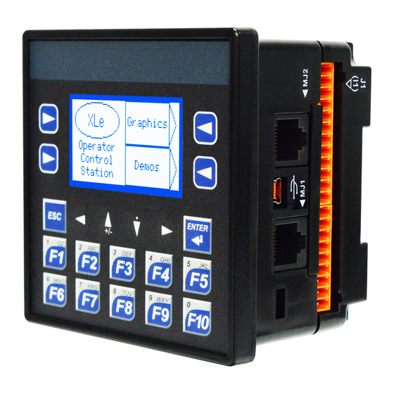
User Manual
for XLE/XLT OCS
HE-XE100, HE-XE102, HE-XE103, HE-XE104, HE-XE105, HE-XE106
HE-XE1E0, HE-XE1E2, HE-XE1E3, HE-XE1E4, HE-XE1E5, HE-XE1E6
HE-XT100, HE-XT102, HE-XT103, HE-XT104, HE-XT105, HE-XT106
HE-XT1E0, HE-XT1E2, HE-XT1E3, HE-XT1E4, HE-XT1E5, HE-XT1E6
HEXE220C100, HEXE220C000, HEXT240C100
HEXE220C112, HEXE220C012, HEXT240C112
HEXE220C113, HEXE220C013, HEXT240C113
HEXE220C114, HEXE220C014, HEXT240C114
HEXE220C115, HEXE220C015, HEXT240C115
HEXE220C116, HEXE220C016, HEXT240C116
HEXE221C100, HEXT241C100
HEXE221C112, HEXT241C112
HEXE221C113, HEXT241C113
HEXE221C114, HEXT241C114
HEXE221C115, HEXT241C115
HEXE221C116, HEXT241C116
MAN0878-09-EN_XLE_XLT_UserManual
Advertisement
Table of Contents
Troubleshooting


Need help?
Do you have a question about the HE-XE100 and is the answer not in the manual?
Questions and answers
I have an HE-XE102WM and would like to reset it to factory defaults (erase existing program), But I don't know the password. Is this posable?