Table of Contents
Advertisement
Quick Links
Find the manuals via the Documentation Search page on
the Horner website.
Part Numbers
Global Part Numbers
XLE - Model 0
XLEe - Model 0 with Ethernet
XLT - Model 0
XLTe - Model 0 with Ethernet
European Part Numbers
XLE - Model 0
XLEe - Model 0 with Ethernet
XLT - Model 0
XLTe - Model 0 with Ethernet
Accessories and Add-Ons
Part #
HE-BAT009
CR2450 Lithium Coin Battery
HE-XCK
Programming Cables
2 channel Analog Output I/O option kit,
HE-XDAC
selectable 0-10V, +/-10V, 4-20mA.
4 channel Analog Output I/O option kit,
HE-XDAC107
selectable 0-10V, +/-10V, 4-20mA.
HE-XKIT
Blank I/O Board
Adapter, RJ45 (8P8C) male to 8-pos-
HE200MJ2TRM
ition terminal strip.
Ferrite core for filtering out electrical
HE-FBD001
noise.
XLE/XLT User Manual - MAN0878
Find the manuals via the Documentation Search page on
the Horner website.
XLE/XLEe & XLT/XLTe - Model 0
MAN1112-20-EN_XLET_Mod0
HE-XE100
HE-XE1E0
HE-XT100
HE-XT1E0
HEXE220C100
HEXE221C100
HEXT240C100
HEXT241C100
Description
No Built-In I/O
Table of Contents
TECHNICAL SPECIFICATIONS
General Specifications
Control and Logic
User Interface
Connectivity
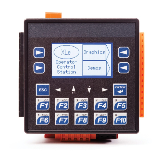
CONTROLLER OVERVIEW
Overview of XLE and XLT
Power Wiring
COMMUNICATIONS
Serial Communication
MJ1 Wiring
MJ2 Wiring
Ethernet
CAN Communications
Dip Switches
DIMENSIONS & INSTALLATION
Dimensions & Panel Cutout
Installation Information
Installation Procedure
Battery Maintenance
SAFETY & MAINTENANCE
Warnings
FCC Compliance
Technical Support
Precautions
Page 1
2
2
2
2
2
3
3
3
4
4
4
4
4
4
4
5
5
5
5
5
6
6
6
6
6
Advertisement
Table of Contents

Related Manuals for HORNER XLE


Summary of Contents for HORNER XLE
- Page 1 XLE/XLEe & XLT/XLTe - Model 0 No Built-In I/O MAN1112-20-EN_XLET_Mod0 Table of Contents TECHNICAL SPECIFICATIONS General Specifications Control and Logic User Interface Connectivity CONTROLLER OVERVIEW Overview of XLE and XLT Power Wiring Find the manuals via the Documentation Search page on COMMUNICATIONS the Horner website. Serial Communication MJ1 Wiring Part Numbers MJ2 Wiring Ethernet Global Part Numbers CAN Communications XLE - Model 0 HE-XE100 Dip Switches...
- Page 2 IEC 6 1131-3 L anguages Ethernet Ethernet v ersions o nly [XLEe & XLTe] Logic Program Size 256kB Ethernet TCP/IP, M odbus T CP, FTP, S RTP, E GD, 0.7ms/kB l ogic ( XLE) Scan R ate Protocols ICMP, ASCII 0.8ms/kB l ogic ( XLT) SmartRail, S martStix, SmartBlock, Digital I nputs ...
- Page 3 CONTROLLER OVERVIEW Overview of XLE and XLT Power Wiring NOTE: The Primary Power Range is 10VDC to 30VDC. Primary Power Port Pins Signal Description Ground Frame Ground Input Power Supply Ground Input Power Supply Voltage DC Input / Frame 1. Function Keys 2. Touchscreen Solid/Stranded Wire: 12-24 awg (2.5-0.2mm) 3. Navigation Keys Strip length: 0.28” (7mm) 4. USB Mini-B Port Torque, Terminal Hold-Down Screws: 4.5 – 7 in-lbs ...
- Page 4 COMMUNICATIONS Serial Communication CAN Communications MJ1 Wiring RS-232 with full handshaking or RS-485 half- duplex RS-485 termination via switches; biasing via soft- ware CAN Pin Assignments MJ1 Pins SIGNAL DESCRIPTION SIGNAL DIRECTION CAN Ground – Black 8 TXD CN_L CAN Data Low – Blue 7 RXD SHLD Shield Ground – None 6 0V GROUND CN_H CAN Data High – White 5 +5V @ 60mA 4 RTS V+ (NC) No Connect – Red 3 ...
- Page 5 DIMENSIONS & INSTALLATION Dimensions & Panel Cutout Installation Procedure 1. Carefully locate an appropriate place to mount the XLE/XLT. Be s ure to leave enough room at the top of the unit for insertion and r emoval of the microSD™ card. 2. Carefully cut the host panel per the diagram, cre- ating a 92mm x 92mm +/-0.1 mm opening into which the XLE/XLT may be installed. If the opening is too large, water may leak into the enclosure, potentially damaging the unit. If the opening is too small, the OCS may not fit through the hole without damage. 3. Remove any burrs and or sharp edges and ensure the panel is not warped in the cutting process. 4. Remove all Removable Terminals from the XLE/XLT. Insert the X LE/XLT through the panel cutout (from the front). The gasket m ust be between ...
- Page 6 T his could cause a d am- two conditions: aging voltage potential between the laptop and controller. 1. This device may not cause harmful interference. Ensure the controller a nd laptop are grounded for max- 2. This device must accept any interference received, includ- imum protection. Consider using a USB isolator due to ing interference that may cause undesired operation. voltage potential differences as a preventative measure. Technical Support North America 1 (317) 916-4274 (877) 665-5666 www.hornerautomation.com techsppt@heapg.com Europe +353 (21) 4321-266 www.hornerautomation.eu technical.support@horner-apg.com Page 6...
Need help?
Do you have a question about the XLE and is the answer not in the manual?
Questions and answers