Table of Contents
Advertisement
Quick Links
12 DC In, 12 DC Out, 17-bit Analog In (mA/V/Tc/mV/RTD), 4 - 12-bit Analog Out
Part Numbers
Global Part Number
European Part Number
User Manual and Add-Ons
Find the documents via the Documentation Search.
Part #
MAN0964
XL4 & XL4 Prime User Manual
MAN1142
Rechargeable Battery Manual
HE-BAT019
Rechargeable 3.6V Lithium Battery
HE-XCK
Programming Cables
2 channel Analog Output I/O option kit,
HE-XDAC
selectable 0-10V, +/-10V, 4-20mA.
4 channel Analog Output I/O option kit,
HE-XDAC107
selectable 0-10V, +/-10V, 4-20mA.
HE-XKIT
Blank I/O Board
Adapter, RJ45 (8P8C) male to 8-pos-
HE200MJ2TRM
ition terminal strip.
Ferrite core for filtering out electrical
HE-FBD001
noise.
Battery Maintenance
The XL4 has an advanced battery system that uses a
rechargeable lithium battery. The battery powers the real
time clock when power is removed, and it is needed for
register data retention. Manual MAN0964 via the Docu-
mentation Search for more details on battery replacement.
XL4 - Model 6
MAN1148-20-EN_XL4_Mod6
HE-XC1E6
HEXT251C116
Description
Table of Contents
Page 1
1
1
1
2
2
2
2
2
3
3
3
4
4
4
5
5
6
6
6
7
7
8
8
9
9
10
10
10
10
10
11
11
11
11
12
12
12
12
12
Advertisement
Table of Contents

Related Manuals for HORNER XL4 6


Summary of Contents for HORNER XL4 6
-
Page 1: Table Of Contents
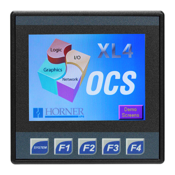
XL4 - Model 6 12 DC In, 12 DC Out, 17-bit Analog In (mA/V/Tc/mV/RTD), 4 – 12-bit Analog Out MAN1148-20-EN_XL4_Mod6 Table of Contents Part Numbers User Manual and Add-Ons Battery Maintenance TECHNICAL SPECIFICATIONS General Specifications Control and Logic User Interface Connectivity CONTROLLER OVERVIEW Overview of OCS Part Numbers Power Wiring Model 6 Specifications Global Part Number HE-XC1E6 Digital DC Input... -
Page 2: Technical Specifications
TECHNICAL SPECIFICATIONS General Specifications User Interface Typical P ower B acklight Display T ype 3.5” T FT Color 239mA @ 1 0V (2.39W) 103mA @ 24V ( 2.47W) 100% Screen B rightness 640cd/m2 ( nits) Power B acklight O ff 18mA @ 2 4VDC ( 0.43W) Resolution QVGA ... -
Page 3: Controller Overview
CONTROLLER OVERVIEW Overview of OCS Power Wiring NOTE: The Primary Power Range is 10VDC to 30VDC. Primary Power Port Pins Signal Description Ground Frame Ground Input Power Supply Ground Input Power Supply Voltage DC Input / Frame Solid/Stranded Wire: 12-24 awg (2.5-0.2mm) Strip length: 0.28” (7mm) Torque, Terminal Hold-Down Screws: 4.5 – 7 in-lbs (0.50 – 0.78 N-m) DC- is internally connected to I/O V-, but is isolated from CAN V-. A Class 2 power supply must be used. 1. Touchscreen Power Up 2. ... -
Page 4: Model 6 Specifications
Model 6 Specifications Digital DC Input Inputs p er M odule 12 I ncluding 4 C onfigurable HSC Inputs Commons p er M odule Input V oltage Range 12VDC / 2 4VDC Absolute M ax. V oltage 30VDC M ax. Input I mpedance 10kΩ ... -
Page 5: Analog Inputs
Analog Inputs Number o f C hannels 0-20mA; 4 -20mA D C; 0 -60mV; 0 -10VDC; Input R anges (Selectable) T/C (Ungrounded): J , K , N , T , E , R , S , B RTD: P T100, PT1000 10V, ... -
Page 6: Wiring: Inputs And Outputs
WIRING: INPUTS AND OUTPUTS Analog Inputs Information Raw input values for channels 1-4 are found in the registers as Integer- type data with a range from 0 – 32000. Analog inputs may be filtered digitally with the Filter Constant found in the Cscape Hardware Configuration for Analog Inputs. Valid filter values are 0-7 and act according to the following chart: Data Values Input Mode: Data Format, 12-bit INT: 0-20mA, 4-20mA 0-32000 0-41V 0-32000 °C or °F may be selected in the Hardware Configuration section in Cscape. The raw value is an integer, T/C & RTD so the user should divide by 10. Digital Inputs Information Digital inputs may be wired in either a Positive Logic or Negative Logic fashion as shown. The setting in the Cscape Hardware Configuration for the Digital Inputs must match the wiring used in order for the correct input states to be registered. When used as a normal input and not for high speed functions, the state of the input is reflected in registers %I1 – %I12. Digital inputs may alternately be specified for use with High Speed Counter functions, also found in the Hardware Configuration for Digital Inputs. Refer to the User Manual via the Documentation Search for more details. ... -
Page 7: Connector Overview
Connector Overview For ease of operability, the high density terminals are divided into more manageable pairs of connectors (J1A + J1B, J2A + J2B, J3A + J3B). To ensure proper installation, connector symbols must match. J1 and J2 Wiring J1 Wiring J2 Wiring Page 7... -
Page 8: J3 Wiring
J3 Wiring NOTE: * Both mA & V outputs are active for each output channel, however, only the configured output type is calibrated (maximum 4 channels simultaneously). J3 Universal Wiring & Wiring Details Wiring Details Solid/Stranded Wire: 1 2-24 awg (2.5-0.2mm2). Strip Length: 0 .28” (7mm). Torque, Terminal Hold-Down Screws: 4 .5 – 7 in-lbs (0.50 – 0.78 N-m). Page 8... -
Page 9: Status Registers
Status Registers Selectable Description Range Bit-wise s tatus r egister e nable: Set % Rx.1 - % Rx.9 h igh t o e nable f or r egisters % R(x+1) t o % R %Rx* (x+9). -
Page 10: Communications
COMMUNICATIONS Serial Communication CAN Communications MJ1/2 Serial Ports 2 Serial Ports on 1 Module Jack (8posn) MJ1: RS-232 w/Full Handshaking MJ2: R S-485 Half-Duplex CAN Pin Assignments SIGNAL DESCRIPTION MJ1 PINS MJ2 PINS CAN Ground – Black SIGNAL DIRECTION SIGNAL DIRECTION CN_L CAN Data Low – Blue SHLD Shield Ground – None CN_H CAN Data High – White GROUND GROUND +5V @ +5V ... -
Page 11: Dimensions & Installation
DIMENSIONS & INSTALLATION XL4 & XL4 Prime Dimensions Installation Information The XL4/XL4 Prime utilizes a clip installation method to ensure a robust and watertight seal to the enclos- ure. Please follow the steps below for the proper installation and operation of the unit. This equipment is suitable for Class I, Division 2, Groups A, B, C and D or non-hazardous locations only. Digital outputs shall be supplied from the same source as the operator control station. Jumpers on connector JP1 shall not be removed or replaced while the circuit is live unless the area is known to be free of ignitable concentrations of flam- mable gases or vapors. Installation Procedure 1. Carefully locate an appropriate place to mount the OCS Be sure to leave enough room at the top of the unit for insertion and removal of the microSD™ card. 2. Carefully cut the host panel per the diagram, cre- ating a 92mm x 92mm +/-0.1mm opening into which theOCS may be installed. If the opening is too large, water may leak into the enclosure, potentially dam- aging the unit. If the opening is too small, the OCS ... -
Page 12: Safety & Maintenance
T his could cause a d am- two conditions: aging voltage potential between the laptop and controller. 1. This device may not cause harmful interference. Ensure the controller a nd laptop are grounded for max- 2. This device must accept any interference received, includ- imum protection. Consider using a USB isolator due to ing interference that may cause undesired operation. voltage potential differences as a preventative measure. Technical Support North America 1 (317) 916-4274 (877) 665-5666 www.hornerautomation.com techsppt@heapg.com Europe +353 (21) 4321-266 www.hornerautomation.eu technical.support@horner-apg.com Page 12...
Need help?
Do you have a question about the XL4 6 and is the answer not in the manual?
Questions and answers