Sign In
Upload
Manuals
Brands
HORNER Manuals
Controller
HE-XE1E2
HORNER HE-XE1E2 PLC Controller Manuals
Manuals and User Guides for HORNER HE-XE1E2 PLC Controller. We have
2
HORNER HE-XE1E2 PLC Controller manuals available for free PDF download: User Manual, Instructions Manual
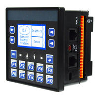
HORNER HE-XE1E2 User Manual (158 pages)
XLE/XLT OCS
Brand:
HORNER
| Category:
Controller
| Size: 4.03 MB
Table of Contents
Preface
2
Limited Warranty and Limitation of Liability
3
Visual Map of Major Tasks and the Key Chapters
4
Table of Contents
5
Chapter 1: Safety / Compliance
9
Safety Warnings and Guidelines
9
Grounding
10
CE Compliance
10
Chapter 2: Introduction
11
Visual Overview of XLE/XLT and Topics Covered in this Manual
11
Figure 02.1 - Visual Overview of XLE/XLT
11
Where to Find Information about the XLE/XLT
12
Connectivity to the XLE/XLT
13
Xle/Xlt
13
Figure 02.2 -Overview of Types of Devices that Can be Connected to XLE/XLT
13
Features of XLE/XLT
14
Accessories
15
Useful Documents and References
15
Opening Cscape Help File
15
Chapter 3: Mechanical Installation
16
Overview
16
Mounting Requirements
16
Mounting Procedures (Installed in a Panel Door)
16
Figure 03.1 - Panel Mounting of the XLE/XLT and Close-Up View of Back
16
Mounting Procedures (Installed on DIN Rail)
17
Figure 03.2 - DIN Rail Mounting of the XLE/XLT
17
Mounting Orientation
18
Panel Cut-Out
18
Figure 03.3 - Orientation of XLE/XLT OCS
18
Figure 03.4 - XLE/XLT Panel Cut-Out
18
Dimensions
19
Figure 03.5 - XLE/XLT Dimensions
19
Factors Affecting Panel Layout Design and Clearances
20
Clearance / Adequate Space
20
Grounding
20
Temperature / Ventilation
20
Orientation
21
Noise
21
Shock and Vibration
21
Panel Layout Design and Clearance Checklist
21
Chapter 4: Electrical Installation
22
Grounding Definition
22
Ground Specifications
22
How to Test for Good Ground
23
Figure 04.1 - Two-Point Ground Connection Test
23
Primary Power Port
24
Figure 04.2 - Power Connector
24
Figure 04.3 - as Viewed Looking at the XLE/XLT
24
Chapter 5: Serial Communications
25
Overview
25
Port Descriptions
25
Wiring
26
Figure 5.1 - MJ1 & MJ2 Serial Ports
26
Termination
27
Biasing
27
Cscape Programming Via Serial Port
27
Ladder-Controlled Serial Communication
27
Configuration Via USB
28
Figure 5.2 - Configuration Via USB
28
Chapter 6: Can Communications
29
Overview
29
Port Description
29
Wiring
30
Cscape Programming Via CAN
30
Figure 06.1 - CAN 1 Port Connector
30
Ladder-Controlled CAN Communication
31
Using CAN for I/O Expansion (Network I/O)
31
Chapter 7: Downloadable Communication Protcols
32
Overview
32
Protocol Config
34
Figure 07.1 - Protocol Config Dialog
34
Network Configuration
35
Device List and Device Configuration
37
Scan List
38
Data Mapping Configuration (Scan List Entry)
39
Chapter 8: Ethernet Communication
41
Ethernet Module Protocols and Features
41
Ethernet System Requirements
41
Ethernet Module Specifications
41
Ethernet Module Configuration
42
Figure 08.1 - Hardware Configuration Dialog
42
Figure 08.2 - Hardware Configuration Dialog
43
Figure 08.3 - Ethernet Module Configuration
44
Ethernet Configuration - IP Parameters
46
Ethernet Module Protocol Configuration
47
Chapter 9 System Settings and Adjustments
48
System Menu - Overview
48
System Menu - Navigation and Editing
48
XLE System Menu
49
Figure 09.1 - XLE System Menu
49
XLT System Menu
50
Figure 09.2 - XLT System Menu
50
System Menu - Details
51
Chapter 10: Removable Media
64
Overview
64
Microsd Cards
64
Figure 10.1 - Installing Removable Memory Card
64
Micro SD File System
65
Using the Removable Media Manager
65
Using Removable Media to Log Data
65
Using Removable Media to Load and Save Applications
66
Using Removable Media to View and Capture Screens
66
Removable Media (RM) Function Blocks in Cscape
67
Removable Media (RM) Features-Program Features
67
Removable Media (RM) Features-Graphic/Screen Editor
68
Removable Media (RM) Features-Additional Configuration
68
Filenames Used with the Removable Media (RM) Function Blocks
69
System Registers Used with RM
70
General I/O
71
Overview
71
Removing the XLE/XLT
71
Figure 11.1 - Removing the Back Cover
71
Chapter 11: General I/O
71
Model I/O Overview
72
Figure 11.2 - Example Jumper Diagram
72
Solid-State Digital Outputs
73
Figure 11.3 - Typical Output Wiring
73
Relay Outputs
74
Figure 11.4 - Relay Fusing
74
Digital Inputs
75
Figure 11.5 - Positive and Negative Inputs
75
Analog Inputs
76
Thermistor Option for Special Orders
76
Common Cause of Analog Input Tranzorb Failure, Models 2, 3, 4, & 5
76
Figure 11.6 - Analog Input Tranzorb - Troubleshooting
76
Universal Analog Inputs
77
Figure 11.7 - Analog Input Configuration (Model 6)
77
Figure 11.8 - Universal Analog in Configuration Screen
78
Analog Outputs
79
Chapter 12: High Speed I/O (Hsc / Pwm)
80
Overview
80
Glossary
81
High Speed Counter (HSC) Functions
82
Frequency
82
Totalize
83
Pulse Width Measurement
85
Period Measurement
86
Quadrature
87
Figure 12.1 - Sync Pulse Mode Illustration
90
HSC Functions Register Map
91
Pulse Width Modulation (PWM) Functions
92
Normal
92
Pwm
92
PWM Output Waveform
95
Figure 12.2 - PWM Output Waveform
95
HSC (High Speed Counter)
96
Stepper Function
96
PWM Functions Register Map
97
PWM Examples
98
STP Examples
99
Chapter 13: User Interface
100
Overview
100
Screen Navigation
100
Figure 13.1 - Typical Screen Jump Object
100
Figure 13.2- Typical Screen Jump Object (XLT)
100
Using Editable Screen Objects
101
Ladder Based Screen Navigation
102
Figure 13.3 - Force and Switch Coils in Ladder Programming
102
Alarms
103
Figure 13.4-Alarm Configuration in Cscape
104
Figure 13.5 - Alarm Object
104
Screen Saver
105
Screen Brightness
105
Chapter 14: Registers
106
Register Definitions
106
Useful %S and %SR Registers
108
Register Map for XLE/XLT I/O
111
Resource Limits
112
Chapter 15: Cscape Configuration
113
Overview
113
Updating Programs from First Generation to Second Generation XLE/XLT
113
Cscape Status Bar
114
Establishing Communications Overview
115
Figure 15.01 - Cscape Connection Wizard Screenshots
116
Figure 15.02 - Cscape Connection Wizard Screenshots
117
Figure 15.04 - Add Target Screenshot in Cscape
118
Communicating Via MJ1 Serial Port
120
Communicating Via on Board Ethernet Port
121
Figure 15.06 - LAN1 Configuration Screen
121
Configuration
122
Figure 15.07 - Module Configuration
122
Digital / HSC Input Configuration
123
Figure 15.08 - Digital / HSC Input Configuration Dialog
123
Digital / PWM Output Configuration
124
Figure 15.09 - Digital / PWM Output Configuration Dialog
124
Analog Input Configuration
125
Figure 15.10 - Analog Input Configuration Dialog
125
Analog Output Configuration
126
Figure 15.11- Analog Output Configuration Dialog
126
Scaling Analog Inputs
127
Figure 15.12 - Scaling Analog Input
127
Chapter 16: Fail - Safe System
129
Overview
129
Figure 16.1- Fail Safe System Menu
129
Settings
130
Backup / Restore Data
130
Figure 16.2 - Backup / Restore Data
130
Figure 16.3- Backup Registers
131
Figure 16.4 - Restore OCS Data
132
Figure 16.5- Clear Backup Data
133
Figure 16.6 - Flow Chart for Automatic Restore
134
Figure 16.7 - Autoload Menu
135
Figure 16.8 - Flow Chart for Autoload
136
Figure 16.9 - Autorun Menu
137
Chapter 17: Clone Unit
138
Overview
138
Clone
138
Figure 17.1- System Menu
138
Figure 17.2 - Clone Unit Menu before Cloning
138
Figure 17.3 - Clone Unit Confirm Screen
139
Figure 17.4 - Clone Unit Files
139
Load Clone
140
Figure 17.5 - Cloning Status
140
Figure 17.6 - System Menu
140
Figure 17.7- Clone Unit Menu after Cloning
141
Figure 17.8 - Load Clone Confirm Screen
141
Chapter 18: Maintenance
142
Firmware Updates
142
Backup Battery
143
Indications the Battery Needs Replacing
143
Figure 18.1 - Replacing the Back-Up Battery
144
Chapter 19: Modbus Communications
145
Modbus Overview
145
Modbus Slave Overview
145
Modbus Master Overview
146
Modbus Addressing Table for XLE/XLT Units
147
Chapter 20: Troubleshooting / Technical Support
149
Connecting to the XLE/XLT
149
Connecting Troubleshooting Checklist
150
Local Controller and Local I/O
151
Local I/O Troubleshooting Checklist
151
Cscan Network
152
Cscan Network Troubleshooting Checklist
152
Removable Media
153
Basic Troubleshooting
153
Technical Support Contacts
153
Index
154
Index of Figures and Tables
157
Advertisement
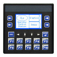
HORNER HE-XE1E2 Instructions Manual (9 pages)
Brand:
HORNER
| Category:
Controller
| Size: 1.68 MB
Table of Contents
Table of Contents
1
Technical Specifications
2
General Specifications
2
Control and Logic
2
User Interface
2
Connectivity
2
Description
3
Controller Overview
3
Overview of XLE and XLT
3
Power Wiring
3
Model 2 Specifications
4
Digital DC Input
4
Digital Relay Outputs
4
Analog Inputs, Medium Resolution
4
Wiring: Inputs and Outputs
5
Analog Inputs Information
5
Digital Inputs
5
Relay Life
5
Jumper Settings for Model 2
5
Back Panel Torque Ratings
5
J1 Wiring - Digital in / Analog in
6
J2 Wiring - Relay out / Analog or Digital in
6
Wiring Details
6
Built-In I/O
6
Analog Input Tranzorb Failure
6
Communications
7
Serial Communication
7
Ethernet
7
CAN Communications
7
Dip Switches
7
Dimensions & Installation
8
Dimensions & Panel Cutout
8
Installation Information
8
Installation Procedure
8
Battery Maintenance
8
Safety & Maintenance
9
Warnings
9
FCC Compliance
9
Technical Support
9
Precautions
9
Advertisement
Related Products
HORNER HE-XE1E0
HORNER HE-XE1E3
HORNER HE-XE1E4
HORNER HE-XE1E5
HORNER HE-XE1E6
HORNER HE-XE100
HORNER HE-XE102
HORNER HE-XE106
HORNER HE-XE103
HORNER HE-XE105
HORNER Categories
Controller
Control Unit
Control Panel
Touchscreen
Modem
More HORNER Manuals
Login
Sign In
OR
Sign in with Facebook
Sign in with Google
Upload manual
Upload from disk
Upload from URL