Table of Contents
Advertisement
Quick Links
FCC NOTICE
This device complies with Part 15 of the FCC Rules.
Operation issubject to the following two conditions:
(1) this device may not cause harmful interference, and
(2) this device must accept any interference received,
including interference that may cause undesired opera-
tion.
NOTE: This equipment has been tested and found to
comply with the limits for a Class A digital device,
pursuant to Part 15 of the FCC Rules. These limits are
designed to provide reasonable protection against
harmful interference when the equipment is operated in
a commercial environment. This equipment generates,
uses, and can radiate radio frequency energy and, if not
installed and used in accordance with the instruction
manual, may cause harmful interference to radio com-
munications. Operation of this equipment in a residen-
tial area is likely to cause harmful interference in which
case the user will be required to correct the interferen-
ce at his own expense.
WARNING: Modifications not expressly approved by
this company could void the user's authority to operate
the equipment.
FCC ID: STG-DFQMX4
* Bluetooth and the Bluetooth logos are trademarks
owned by Bluetooth SIG, Inc., U.S.A. and licensed
to LinTech GmbH, Berlin Germany.
Worldwide Headquarters
European Headquarters
Raytek GmbH
Raytek Corporation
Berlin, Germany
1201 Shaffer Road, PO Box 1820
Santa Cruz, CA 95061-1820 USA
Tel: +49 30 4 78 00 80
Tel: +1 831458 1110
Fax: +49 30 4 71 02 51
Fax: +1 831425 4561
raytek@raytek.de
solutions@raytek.com
www.raytek.com
United Kingdom
Tel: +44 1908 63 08 00
Raytek China Company
Fax: +44 1908 63 09 00
ukinfo@raytek.com
Beijing, China
Tel: +86 10 64 39 22 55
Fax: +86 10 64 37 02 85
France
info@raytek.com.cn
Tel: +33 1 64 53 15 40
Fax: +33 1 64 53 15 44
Raytek Japan, Inc.
info@raytek.fr
Tokyo, Japan
Tel: +81 3 57 33 60 65
Fax: +81 3 57 33 60 99
info@raytekjapan.co.jp
South American Headquaters
Raytek do Brasil
Sorocaba, SP Brasil
Tel: +55 15 32 17 60 46
Fax: +55 15 32 17 56 94
info@raytek.com.br
MX4
™
Raytek warrants this product to be free from defects in material and
workmanship under normal use and service for a period of one year*
from date of purchase except as hereinafter provided. This warranty
TD
extends only to the original purchaser (a purchase from Raytek or
Raytek's licensed distributors is an original purchase). This warranty
shall not apply to fuses or batteries. Factory calibration is warranted for
Bluetooth
a period of one year. The warranty shall not apply to any product which
®
has been subject to misuse, neglect, accident, or abnormal conditions of
operation or storage. Should Raytek be unable to repair or replace the
product within a reasonable amount of time, purchaser's exclusive
remedy shall be a refund of the purchase price upon return of the
product.
In the event of failure of a product covered by this warranty, Raytek will
repair the instrument when it is returned by the purchaser, freight
prepaid, to an authorized Service Facility within the applicable
warranty period, provided Raytek's examination discloses to its
satisfaction that the product was defective. Raytek may, at its option,
replace the product in lieu of repair. With regard to any covered
product returned within the applicable warranty period, repairs or
replacement will be made without charge and with return freight paid
by Raytek, unless the failure was caused by misuse, neglect, accident,
or abnormal conditions of operation or storage, in which case repairs
will be billed at a reasonable cost. In such a case, an estimate will be
submitted before work is started, if requested.
The foregoing warranty is in lieu of all other warranties, expressed or
implied, including but not limited to any implied warranty of
merchantability, fitness, or adequacy for any particular purpose or use.
Raytek shall not be liable for any special, incidental or consequential
damages, whether in contract, tort, or otherwise.
Raytek gewährt für dieses Produkt eine Garantie von einem Jahr*
ab dem Kaufdatum. Der Hersteller garantiert, daß das Produkt im
genannten Zeitraum bei ordnungsgemäßer Anwendung und Wartung
keine Material- und Bearbeitungsfehler aufweist. Ausnahmen sind im
folgenden festgelegt.
HIGH PERFORMANCE
Diese Garantie gilt nur für den Ersterwerber (der Erwerb des Produktes
INFRARED THERMOMETER
von Raytek oder einem autorisierten Raytek-Händler gilt als
Ersterwerb). Die Garantie erstreckt sich nicht auf Sicherungen oder
Batterien. Für die im Werk vorgenommene Kalibrierung gewährt
Raytek eine Garantiefrist von einem Jahr. Die Garantie schließt keine
Produkte ein, die mißbräuchlich oder fahrlässig verwendet, beschädigt
oder unzulässig betrieben oder gelagert wurden.
Die vorstehenden Garantiebedingungen ersetzen alle anderen eventuell
gemachten ausdrücklichen oder stillschweigenden Zusicherungen.
Raytek übernimmt keine Haftung für einen besonderen, beiläufigen
oder mittelbaren Schaden, gleich ob dieser im Rahmen des Vetrages,
Rev. H1
durch eine unerlaubte Handlung oder auf andere Weise entstanden ist.
01/2005
57701-E1
* European Union (EU): two years/zwei Jahre
WARRANTY
GARANTIEBEDINGUNGEN
Advertisement
Table of Contents

Related Manuals for RayTek MX4TD


Summary of Contents for RayTek MX4TD
- Page 1 Tel: +86 10 64 39 22 55 In the event of failure of a product covered by this warranty, Raytek will pursuant to Part 15 of the FCC Rules. These limits are Fax: +86 10 64 37 02 85...
- Page 2 Los costes del envío de vuelta al cliente corren a cargo de Raytek. En el caso de que el defecto se deba a una manipulación incorrecta, negligencia, daño causado por agentes exteriores, almacenamiento o empleo no autorizados, recibirá...
- Page 3 HIGH PERFORMANCE INFRARED THERMOMETER...
-
Page 5: Table Of Contents
Table of Contents Introduction Features/Accessories Functions (User interface) Display Batteries Measurement (Quick Start) Measurement (Continuous) Measurement (Spot size) Selecting a function Laser On/Off Emissivity explained Emissivity adjustment Emissivity Table of Values Emissivity Unknown value Mode Maximum Mode Minimum Mode Difference Mode Average Mode Probe connection Setup High Alarm... -
Page 7: Introduction
INTRODUCTION We hope you enjoy using your infrared thermometer! It measures the amount of infrared energy emitted by a target object, and calculates the temperature of that object´s surface. FEATURES Your thermometer includes: - Laser sighting - Adjustable emissivity - High/Low Alarm - MAX, MIN, DIF, AVG - Data Logger (100 points) - Trigger lock... -
Page 8: Functions (User Interface)
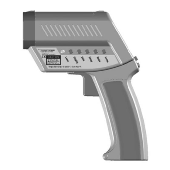
FUNCTIONS USER INTERFACE Function keys and display: (A) Visual and audible alarm (B) Display (C) Up and Down keys (D) Enter (E) Handle and battery compartment (DIP switches for adjustments are inside handle) (F) Trigger (G) Tripod mount (H) 6 main function keys DISPLAY Displayed functions: (1) Laser condition /... -
Page 9: Batteries
BATTERIES To open the battery compartment, press gently on the top part of the handle (1) to release the catch (2) and pivot the grip as shown in the figure. Orient the batteries (two alkaline R6 (AA, UM3)) as shown on the housing. MEASUREMENT QUICK START To take a temperature... -
Page 10: Measurement Continuous
MEASUREMENT CONTINUOUS Open the battery compart- ment and switch LOCK "on" to lock the unit on. You may mount the unit on a tripod, using the tripod mount. Pull the trigger for continuous temperature measurement. (The laser will not be locked on.) To unlock, switch LOCK off. -
Page 11: Selectinga Function
SELECTING A FUNCTION To select a function, first turn the unit on by pulling the trigger (F). Then push the button of the desired function (H). To change functions, press ENTER or the function button again, and then the new function button. -
Page 12: Emissivity Explained
EMISSIVITY EMISSIVITY EXPLAINED The amount of infrared energy radiated by an object depends on its emissivity and its Reflected energy temperature. Emitted energy The emissivity depends on the material and its surface characteristics. For more EMISSIVITY Transmitted energy accurate readings, adjust Target the emissivity value for the type of material being... -
Page 13: Emissivity Table Of Values
EMISSIVITY TABLE OF VALUES To choose the emissivity of a material, press EMISS (P). The display shows a material name (7), an emissivity value, and the calculated temperature value (5). To choose another material, use the Up and Down keys (C). Press ENTER (D) to activate this setting. -
Page 14: Mode Maximum
MODE MAXIMUM To activate the MAX mode, press MODE (O) until the MAX symbol appears (9). The measured maximum temperature is displayed (3) as long as the trigger is pulled or locked on. The real time temperature is shown in the lower part of the display (NORM) (7). -
Page 15: Mode Difference
MODE DIFFERENCE To activate the DIF mode, press MODE (O) until the DIF symbol (9) appears. The difference between the measured max and min temperatures is displayed (3) as long as the trigger is pulled or locked on. The real time temperature is shown in the lower part of the display (NORM) (7). -
Page 16: Mode Probe Connection
MODE TC/NTC PROBE CONNECTIONS Open the battery compart- ment and set the switches ON or Off according to the desired probe type. (10) NTC - thermistor (11) TC - thermocouple (12) Thermocouple type J (13) Thermocouple type K Connect the probe to the input (U). -
Page 17: Setup High Alarm
SETUP HIGH ALARM The high alarm (HiAl) generates an audible and visual (flashing LED (A) and laser) alarm if the temperature is above the setpoint. To set the alarm value (6), Press SETUP (N) once, and use the Up and Down keys (C). -
Page 18: Setup Time
SETUP TIME To set the time, press SETUP (N) three times. Change the time (2) using the Up and Down keys (C). Then press ENTER (D) for each time segment to activate this time setting. The time appears on the display, is stored within the data logger, and is part of the printer output. -
Page 19: Setup Offset
SETUP OFFSET This function is used with a selected emissivity to add or subtract an offset value (±10°C/±18°F) to the temperature value. Press the Setup button (N) until "Offset" appears in the display. With the arrow keys (C) adjust the display to the corrected value. -
Page 20: Data Logger (How To Store Data)
DATA LOGGER HOW TO STORE DATA By pressing the ENTER button (D) the LOG function (6) appears on the display. Pull the trigger (F) and hold it. Aim at the target. Be sure that the laser sighting is inside the target. Gently release the trigger to record the temperature. -
Page 21: Display (Graphic Display)
DISPLAY GRAPHIC DISPLAY The graphic display (4) shows the temperature as a picture. The last ten measurements are shown (B). It is possible to choose between Auto Range and Manual Range. In manual range the user defines the beginning and ending temperature points of the graph. -
Page 22: Display Begin (Man. Range)
DISPLAY BEGIN (Man. Range) To set the BEGIN value for the graphic display (Man Range is activated), press DISPLAY (L) until “Begin” is shown at the status bar. Use the Up and Down keys (C) to select the value (6). DISPLAY (Man. -
Page 23: Display Cycle
DISPLAY CYCLE CYCLE allows the adjustment of the display interval. Press DISPLAY (L) until Cycl.: (7) is shown at the status bar. To select the interval time, use the Up and Down keys (C). The default value is pre-set for 0.2 sec. SETTINGS (PART 1) Change the setting in the... - Page 24 SETTINGS (PART 2) Factory Defaults DIP-Switch Settings Lock Lock C/ F C/ F Buzzer Buzzer Backlight Backlight Set Default Set Default Ltd. Access Ltd. Access Laserflash Laserflash Printer Printer Digi/Ana Digi/Ana Time/Date Time/Date NTC/TC NTC/TC TC-J/TC-K TC-J/TC-K Celsius setting shown Fahrenheit setting shown Backlight: Backlight On or Off.
- Page 25 SETTINGS (PART 3) PRINTER Printer: (ON) The printer’s data output (RS232) is working as long as the trigger is pulled. The protocol includes: (14) Date (15) Time (16) Target temperature - infrared (17) Target temperature- probe "X" See software manual for other printout options.
- Page 26 SETTINGS (PART 4) Digi/Ana: Digital or Analog output. Digital (RS232) output must be used with the printer or a PC. Analog output (mV/°) is usually used for data logging. Time/Date: Time or date shown on the display. SETTINGS (PART 5) CONTACT PROBES NTC/TC: Thermistor (NTC) or...
-
Page 27: Appendix A: Special Order Models
APPENDIX A SPECIAL ORDER MODELS Close-Focus Model CLOSE FOCUS MODEL Optical Chart DISTANCE: SENSOR TO OBJECT (IN) 7.9 9.8 0.24 IN @ 11.8 IN 2.81 0.93 0.75 0.62 0.49 0.37 Close Focus 12,3 9,2 15,5 18,7 6 mm @ 300 mm 200 250 1000 DISTANCE: SENSOR TO OBJECT (mm) -
Page 28: Appendix Btroubleshooting
APPENDIX B TROUBLESHOOTING TROUBLESHOOTING Code Problem Action Target temperature is over Select target within unit’s under range specs EEPROM-Err EEPROM error Contact Factory CalAreaErr calibration errors Contact ProbCalEr Factory Battery icon Battery is low Replace flashes or Batteries LowBatt Blank display Battery is dead Replace Batteries... -
Page 29: Appendix Cmaintenance
APPENDIX C MAINTENANCE Lens Cleaning: Blow off loose particles using clean compressed air. Brush remaining debris away with a camel’s hair brush. Wipe the surface with a moist cotton swab. The swab may be moistened with water or a water based glass cleaner. -
Page 30: Appendix Dlaser Warning Label
APPENDIX D LASER WARNING LABEL CAUTION! Do not stare into beam! Avoid indirect exposure via reflective materials! SERIAL NUMBER LABEL Manufacturer, Address Made in Germany: Month, Year Model: XXXXXXX Serial: 000000-0000-0000 Power Requirements 3 V... - Page 31 APPENDIX E CAUTIONS Avoid static electricity, arc welders, and induction heaters. Keep away from very strong EMF (electromagnetic fields). Don’t leave the unit on or near objects of high temperature. WARNING: DO NOT touch live voltage with contact probe. Use the wrist strap for cable support.
-
Page 32: Appendix E: Cautions
APPENDIX E CAUTIONS (cont.) Thermal Shock Avoid abrupt changes in temperature. If this occurs, allow 40 minutes for thermal stabilization before use to prevent the possibility of inaccurate temperature readings. Use only the power supply from the manufacturer. -
Page 33: Appendix F: Emissivities Table
APPENDIX F EMISSIVITIES Aluminum* 0.30 Asbestos 0.95 Asphalt 0.95 Basalt 0.70 Brass* 0.50 Brick 0.90 Carbon 0.85 Ceramic 0.95 Concrete 0.95 Copper* 0.95 Dirt 0.94 Frozen food 0.90 Hot food 0.93 Glass (plate) 0.85 0.98 Iron* 0.70 Lead* 0.50 Limestone 0.98 0.94 Paint... -
Page 34: Specifications
SPECIFICATIONS Temperature Range - 30 to 900°C (- 25 to 1600°F) Display Resolution 0.1°C (0.2°F) Accuracy ± 0.75% of reading or (Infrared) ± 0.75K (± 1,5°F), whichever is greater at 25°C (77°F) ambient temperature, ± 2K (± 4°F) for targets below -5°C (23°F) Ambient derating <... -
Page 35: Factory Defaults
SPECIFICATIONS (Cont.) Power 2 x 1.5 V Alkaline Type AA Battery Life 13 hrs. (50% laser and 50% backlight on) 7.5 V > 200 mA (Using the power supply Power supply (External) the display automatically switches on) Dimensions 200 x 170 x 50 mm (7.9 x 6.7 x 2 inches) Tripod Mount 1/4”-20 UNC FACTORY DEFAULTS... -
Page 36: Nist/Dkd Ce Conformity
CE CONFORMITY This instrument conforms to the following standards: EMC: - EN 61326-1 Safety: - EN 61010-1:1993 / A2:1995 - EN 60825-1:1994 This product herewith complies with the requirements of the EMC Directive 89/336/EEC and the Low Voltage Directive 73/23/EEC. This instrument conforms to the Standards of the European Community. - Page 37 Infrared Thermometer with LinTech* Bluetooth module 6. Press the Setup button In the display, a framed lightning This infrared thermometer allows wireless data transfer with the aid of Bluetooth technology. and then the Down button symbol points to the Bluetooth System requirements: below the display to end the module in active mode and the...
- Page 38 Serial Ports. Note the number of the Here you can give the thermometer a name and change FCC NOTICE connected ComPort. the PIN. Now start the BlueTool Attention: Be sure to make a note of this PIN, because This device complies with Part 15 of the FCC Rules. application, enter the you will be asked to provide it for encrypted transmissions Operation issubject to the following two conditions:...
Need help?
Do you have a question about the MX4TD and is the answer not in the manual?
Questions and answers