
Related Manuals for Wohler RMTF-170-3G-RM


Summary of Contents for Wohler RMTF-170-3G-RM
-
Page 1: User Guide
RMTF-170-3G-TT RMTF-170-3G-RM 17.3” Audio/Video Tabletop/Rack Mount Monitors User Guide User Guide Part Number 821824, Revision A... - Page 2 In no event will Wohler Technologies, Inc. be liable for direct, indirect, special, incidental, or consequential damages resulting from any defect in the hardware, software, or its documentation, even if advised of the possibility of such damages.
-
Page 3: Table Of Contents
TABLE OF CONTENTS Contents User Guide ..................1 TABLE OF CONTENTS................3 Contents ......................3 CHAPTER 1: Installation ................4 Introduction ....................4 Overview....................4 Features ....................4 Safety......................4 Instructions ...................4 Safety Symbols..................5 Mounting....................5 Heat Dissipation..................6 Sympathetic Vibration................6 Mechanical ....................6 Electrical Interference ................6 Power ....................6 Compliance .....................7 FCC ......................7 ICES-003 ....................7 CHAPTER 2: Local Operation ..............8... -
Page 4: Chapter 1: Installation
For use outdoors, an optional Sun Shade (part number 829201) is available for the RMTF-170-3G-TT. The RMTF-170-3G-TT is a tabletop monitor and the RMTF-170-3G-RM is a rack mounted monitor. Except for the mounting style, these monitors are identical, so for convenience, this manual will generally only refer to them as RMTF-170-3G. -
Page 5: Safety Symbols
Please adhere to the clearances listed in Table 1- The RMTF-170-3G-RM is designed to be mounted in 6RU of a standard 19" rack. It may be tilted forward for easier viewing. Position either unit at ear/eye level for best high frequency response and visual observation of the display screen. -
Page 6: Heat Dissipation
Table 1-1: Recommended Clearances Clearance Surface 24” Front 3” Rear 2” Sides 1.75” Top and Bottom (if near other equipment) 0” Top and Bottom (if no other equipment) Heat Dissipation The ambient temperature near the product should not exceed 40° Celsius (104° Fahrenheit). -
Page 7: Compliance
50/60Hz) through the IEC connector provided on the rear panel. Alternately, it can be powered from a camera battery, which installs on the rear panel. When the mains plug or appliance coupler is used as the disconnect device, the disconnect device should remain operable. Compliance This equipment has been tested and found to comply with the limits for a Class A digital device, pursuant to part 15 of the FCC Rules. -
Page 8: Chapter 2: Local Operation
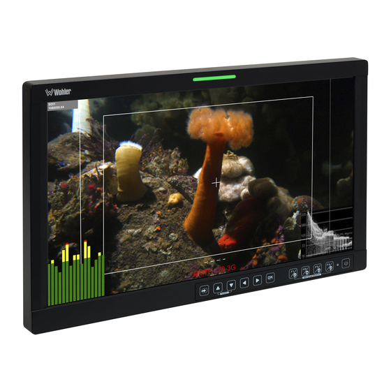
CHAPTER 2: Local Operation The RMTF-170-3G front and rear panels are described in this chapter. Front Panel Figure 2–1: Front Panel Layout 1. Tally Lights: This tri-color (red/green/amber) light is controlled through a RJ45 connector on the rear panel. For more information about the RJ45 connector, refer to the Rear Panel section of this chapter. -
Page 9: On-Screen Display Features
various connectors on the rear panel. The currently selected input source is indicated when the Input button is pressed. Repeated presses change the input source. 5. F1/U1, F2/U2, F3/U3, F4/U4 Function/User Keys: These keys are dual purpose. Momentarily pressing F1, F2, F3, or F4 will activate the assigned function. - Page 10 Audio level meter displays, for up to sixteen channels, can be displayed on either the left or the right of the display. They can show VU, PPM (PK) or both with assignable -20db or -18db reference levels. Waveform (Y or Line), Vectorscope, or Histogram can be shown in various positions almost anywhere on the screen.
-
Page 11: Rear Panel
7. Timecode: The de-embedded timecode from the HD/SD-SDI source displays on the lower part of the screen. The timecode setting is located in the Config Menu. Refer to Table 2-9. 8. Waveform/Vectorscope/Histogram: These can be displayed only for SDI signals. The waveform and vector of the input signal display are configurable in the Config Menu. - Page 12 compliant with SMPTE 424M, SMPTE 259M, SMPTE292M/ITU-R BT601. It can be viewed using the SDI1 selection on the Input button menu. 2. SDI 1 Out: This connector provides a regenerated duplicate of the SDI 1 In signal. This connection is compliant with SMPTE 424M, SMPTE 259M, SMPTE292M/ITU-R BT601.
-
Page 13: Rear Panel Connectors
Rear Panel Connectors The following figure and table detail the connections of the RS-485 connectors on the rear panel. The tables are also silkscreened on the rear panel of the unit for your convenience. Figure 2-4 RS-485 Pinout Table 2-2: RS-485 I/O Connections RS-485 Terminal Name 1, 2 Tx- (pair A) -
Page 14: Quick Menu
Quick Menu The Quick Menu provides quick access to a few commonly used features, as listed in Table 2-3. The Quick Menu appears as shown in Figure 2-6. Figure 2-6: Quick Menu - Volume Setting The following is a description of how to use the Quick Menu: 1. -
Page 15: Osd Menus
8. Press the Left button to back out of any submenu, and finally to remove the OSD Menus from the screen. OSD Menus The following tables describe the information and settings available in the OSD Menu system. Use the instructions in the previous section to navigate the menus. Table 2-4: Status Display Menu Structure Status Display Parameters... - Page 16 Table 2-5: Input Config Menu Structure Input Config Parameters Default Value Domain Range Description SDI IN1 OFF, ON Enables or disables SDI IN2 OFF, ON the input choices available in the VIDEO OFF, ON Input Select Menu HDMI OFF, ON Only for NTSC NTSC PHASE -50 to 50...
- Page 17 CAMERA SDR Set a LUT from the CAMERA LUT TYPE CAMERA SDR CAMERA HDR corresponding list. USER Load the selected CAMERA SDR Refer to Table 2-8 SDR LUT. Load the selected CAMERA HDR Refer to Table 2-8 HDR LUT. Load a custom LUT USER USER1 USER1 - USER16...
- Page 18 RED_L3G10RWG_Rec709_R2_V1.13 RED_L3G10RWG_Rec709_R3_V1.13 RED_L3G10RWG_Rec709_R4_V1.13 Sony_SLog2SGamut_LCRec709 Sony_SLog2SGamut_LCRec709A Sony Sony_SLog3SG3Cine_LCRec709 Sony_SLog3SG3Cine_LCRec709A ARRI_LogC_HLG_Rec2020 ARRI_LogC_PQ_Rec2020 Canon_Clog2Cin_HLG_Rec2020 Canon_Clog2Cin_PQ_Rec2020 Canon_Clog3Cin_HLG_Rec2020 Canon_Clog3Cin_PQ_Rec2020 Panasonic_VLog_HLD_Rec2020 OSEE Panasonic_VLog_PQ_Rec2020 RED_L3G10_HLG_Rec2020 RED_L3G10_PQ_Rec2020 Sony_SLog3_Cin_HLG_Rec2020 Sony_SLog3_Cin_PQ_Rec2020 Sony_SLog3_SG3_HLG_Rec2020 Sony_SLog3_SG3_PQ_Rec2020 Table 2-8: Gamma Range vs Camera LUT Camera LUT Gamma Range 1.8, 2.2, 2.4, 2.6, 2.8 CAMERA SDR BT.1886 CAMERA HDR PQ, HLG...
- Page 19 Table 2-9: User Config Menu Structure User Config Default Parameters Domain Range Description Value USER1 Apply the current USER USER2 User Configuration USER1 PRESET USER3 settings to one of the USER4 four possible Presets. CAMERA LUT Set up the F1/U1 BLUE ONLY SCAN Function key action.
- Page 20 MODE1: meters only DISPLAY Select the appearance MODE1 MODE2: meters with MODE of the meters. channel numbers and frame METER 0 = 100% Set the opacity of the OPACITY 1 = 50% audio meters. Menu Page 3 Enable or disable the display of the markers MARKER OFF, ON...
- Page 21 Menu Page 4 WAVEFORM VECTOR Set the type of WFM FORM WF, WIDE waveform / vector TYPE HDR WFM display. SMALL WAVEFORM Set the size of the SMALL MEDIUM SIZE waveform display. LARGE SMALL: LEFT UP, CENTER UP, RIGHT UP, RIGHT CENTER, RIGHT DOWN, CENTER DOWN,LEFT DOWN,...
- Page 22 Menu Page 5 OFF: Normal Video GRAY: Image is in gray mode and Enable or Disable Focus displays edge of Assist and set mode. images with color FOCUS STANDARD selected in Focus When Focus Level value ASSIST Color. is exceeded, the edge detected will be in the COLOR: Displays edge Focus Color.
- Page 23 IF YOU ARE MONITOR UNSURE OF WHETHER TO PERFORM A FACTORY RESET, RESET CLICK CANCEL AND THEN CONTACT WOHLER TECNICAL SERVICE FOR ADVICE. UPGRADE Use this selection to upgrade the firmware. Follow the FIRMWARE directions on the screen.
- Page 24 Table 2-10: IMD Menu Structure IMD Menu Parameters Default Value Domain Range Description Set whether to IMD DISPLAY ON, OFF enable the IMD. TSL3.1 Select an IMD IMD PROTOCOL LOCAL TSL4.0 protocol. LOCAL (Up to 16 characters of Set the IMD IMD CHARACTER RMTF-170-3G text for static LOCAL message.*...
-
Page 25: Chapter 3: Technical Info
CHAPTER 3: Technical Info Table 3–1: Specifications Specification Values/Domains AC Power Requirements 100 V to 240 VAC ± 10%, 50/60Hz AC Power Consumption 14 Watts DC Power Requirements 11 - 17 VDC @ 3A 16.6” H x 10.4” W x 1.9” D Dimensions 422 mm H x 264 mm W x 49 mm D Weight... -
Page 26: Supported Video Formats
Figure 3–1: RMTF-170-3G Series Block Diagram Tally Light RS-485 UMD / Tally In / Out Camera LUT / SW Update LCD 17" 16:9 With 16-Channel Inputs / Outputs Video Decoding Audio Meters 3G/HD/SD-SDI 1 In 3G/HD/SD-SDI 1 Out 3G/HD/SD-SDI 2 In Input Select CVBS Video In... - Page 27 Table 3-2: Video Formats Format Signal Format Video HDMI 480i60 576i50 720p24/23.98 720p25 720p30/29.97 720p50 720p60/59.94 1080sf24/23.98 1080sf25 4:2:2 YCbCr 10 bit 1080sf29.97 1080sf30 1035i60/59.94 1080i50 1080i60/59.94 1080p24/23.98 1080p25 1080p30/29.97 1080i50 4:2:2 YCbCr 12 bit 4:4:4 YCbCr 10 bit 1080i60/59.94 4:4:4 YCbCr 12 bit 1080p24/23.98 4:4:4 RGB 10 bit...
Need help?
Do you have a question about the RMTF-170-3G-RM and is the answer not in the manual?
Questions and answers