
Related Manuals for Wohler RMT-200-HD


Summary of Contents for Wohler RMT-200-HD
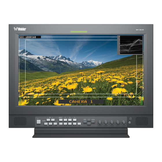
- Page 1 RMT-200-HD 20-Inch High Definition Video Monitor User Guide Part Number 821700, Revision F...
- Page 2 In no event will Wohler Technologies, Inc. be liable for direct, indirect, special, incidental, or consequential damages resulting from any defect in the hardware, software, or its documentation, even if advised of the possibility of such damages.
-
Page 3: Table Of Contents
This monitor comes with many in-monitor display features including IMD, tally, time-code, format display, waveform and area/title safe. The RMT-200-HD also provides a host of audio tools including level metering and built-in speaker monitoring of its dual stereo analog inputs or SDI embedded audio. -
Page 4: Safety Instructions
R M T - 2 0 0 - H D U s e r G u i d e S a f e t y I n s tr u c ti o n s Safety Instructions Read, keep, and follow all of these instructions; heed all warnings. Do not use this equipment near water. -
Page 5: Unpacking And Installation
U n p a c k i n g a n d I n s t a l l a t i o n Unpacking and Installation Unpack the RMT-200-HD monitor and inspect for any apparent physical damage that may have occurred in transit. In addition to the monitor, the package should contain: •... -
Page 6: Fcc Compliance
R M T - 2 0 0 - H D U s e r G u i d e F C C C o m p l i a n c e FCC Compliance This equipment has been tested and found to comply with the limits for a Class A digital device, pursuant to part 15 of the FCC Rules. -
Page 7: Specifications
Audio decoding and display of up to eight channels of SDI • Full gamma color calibration Specifications Physical Specifications Table 1–1 lists the specifications for the RMT-200-HD monitor. Table 1–1 Monitor Specifications Specifications Value/Domain Power 40 W, 110/220 AC (50 to 60 Hz) Dimensions 19.38”... - Page 8 R M T - 2 0 0 - H D U s e r G u i d e S p e c if i c a ti o n s Table 1–1 Monitor Specifications (Continued) Specifications Value/Domain 1 HD/SD-SDI Re-clocked active loop through Outputs 2 Audio selected embedded or external audio 20.1”...
- Page 9 RMT-200-HD User Guide S p e ci f i c a t i o n s Figure 1–2 Rear View Input/Output Specifications Table 1–2 Signal Inputs, Frame Rate, and Color Matrix Overscan Native Full Normal Frame Color Signal Type Rate...
- Page 10 1600x1200 — — WUXGA — — — — 1920x1200 — — Table 1–3 below lists the signal formats that can be displayed on the RMT-200-HD. Table 1–3 Usable Input Signals Format Video YPbPr HDMI NTSC — — — — —...
- Page 11 RMT-200-HD User Guide S p e ci f i c a t i o n s Table 1–3 Usable Input Signals (Continued) Format Video YPbPr HDMI — — — — 1035I60 — — — — 1080I60 — — — —...
- Page 12 R M T - 2 0 0 - H D U s e r G u i d e S p e c if i c a ti o n s Table 1–4 Button/Signal-Terminal Relationships (Continued) Relationship Input Signal Source Function Video Ypbpr...
- Page 13 RMT-200-HD User Guide S p e ci f i c a t i o n s Table 1–6 Analog Video Input Specifications Parameter Value 75 Impedance Input Level 1 Vp-p nominal Maximum Input Level 2.5 Vp-p centered @ 0V Table 1–7...
-
Page 14: Using The Rmt-200-Hd
U s i n g t h e R M T - 2 0 0 - H D Using the RMT-200-HD Front Panel The RMT-200-HD monitor provides a variety of in monitor data including signal type, waveform, IMD (In-Monitor Display), audio meters, and time code. It also includes a three-color tally light above the display. - Page 15 RMT-200-HD User Guide U s i n g t h e R M T -2 0 0 - H D • Audio Levels: Levels are displayed on up to eight meters in pairs as two or four meters on each side.
- Page 16 R M T - 2 0 0 - H D U s e r G u i d e U s i n g t h e R M T - 2 0 0 - H D • SDI Input 1/2 (Button/Indicator): This indicator glows green when this input is selected for display on the monitor.
- Page 17 RMT-200-HD User Guide U s i n g t h e R M T -2 0 0 - H D Rotary Knob/Indicators The rotary knobs on the right side of the monitor’s control panel have multiple functions most of which are very similar and are listed immediately below: Pushing the knob: Displays the current setting.
- Page 18 R M T - 2 0 0 - H D U s e r G u i d e U s i n g t h e R M T - 2 0 0 - H D Figure 1–5 Rear Panel (Left Side Top) •...
- Page 19 RMT-200-HD User Guide U s i n g t h e R M T -2 0 0 - H D Figure 1–6 Rear Panel (Left Side Bottom) • Analog Audio Input 1: Input jacks for the analog audio signal. •...
- Page 20 R M T - 2 0 0 - H D U s e r G u i d e U s i n g t h e R M T - 2 0 0 - H D Figure 1–7 GPI/Tally Light RJ45 Connector Pin Map Table 1–10 GPI/Tally Lamp Color/Pin Designations Tally Lamp Color...
- Page 21 RMT-200-HD User Guide U s i n g t h e R M T -2 0 0 - H D Figure 1–8 DB9 Connector Pin Map Figure 1–9 RS485 RJ45 Connector Pin Map Table 1–12 RS485 Pin Out RS485 Out Terminal...
-
Page 22: Using The Osd Menu
R M T - 2 0 0 - H D U s e r G u i d e U s in g t h e O SD M e n u Using the OSD Menu A description of how to use the follows. - Page 23 RMT-200-HD User Guide U s i n g t h e O S D M e n u Table 1–13 OSD Menu Structure Default Menu Parameters Domain Range Value FORMAT COLOR TEMP COMPONENT Display only; Non-selectable. The values vary LEVEL...
- Page 24 R M T - 2 0 0 - H D U s e r G u i d e U s in g t h e O SD M e n u Table 1–13 OSD Menu Structure (Continued) Default Menu Parameters Domain Range Value...
- Page 25 RMT-200-HD User Guide U s i n g t h e O S D M e n u Table 1–13 OSD Menu Structure (Continued) Default Menu Parameters Domain Range Value Sets the area marker mat transparency, where: • = Normal background, use...
- Page 26 R M T - 2 0 0 - H D U s e r G u i d e U s in g t h e O SD M e n u Table 1–13 OSD Menu Structure (Continued) Default Menu Parameters Domain Range Value...
- Page 27 RMT-200-HD User Guide U s i n g t h e O S D M e n u Table 1–13 OSD Menu Structure (Continued) Default Menu Parameters Domain Range Value Displays the format and scan mode are displayed, where: •...
- Page 28 R M T - 2 0 0 - H D U s e r G u i d e U s in g t h e O SD M e n u Table 1–13 OSD Menu Structure (Continued) Default Menu Parameters Domain Range Value...
-
Page 29: Technical Functional Overview
RMT-200-HD User Guide T e c h n i c a l F u n c t i o n a l O v e r vi e w Technical Functional Overview Figure 1–10 below illustrates the overall functionality of the RMT-200-HD.
Need help?
Do you have a question about the RMT-200-HD and is the answer not in the manual?
Questions and answers