
Subscribe to Our Youtube Channel
Related Manuals for Wohler RMT-170e-HD


Summary of Contents for Wohler RMT-170e-HD
- Page 1 RMT-170e HD Series • RMT-170e-HD • RMT-170e-SD 17-Inch High Definition Video Monitors User Guide Part Number 821042, Revision A...
-
Page 2: Customer Support
In no event will Wohler Technologies, Inc. be liable for direct, indirect, special, incidental, or consequential damages resulting from any defect in the hardware, software, or its documentation, even if advised of the possibility of such damages. -
Page 3: Table Of Contents
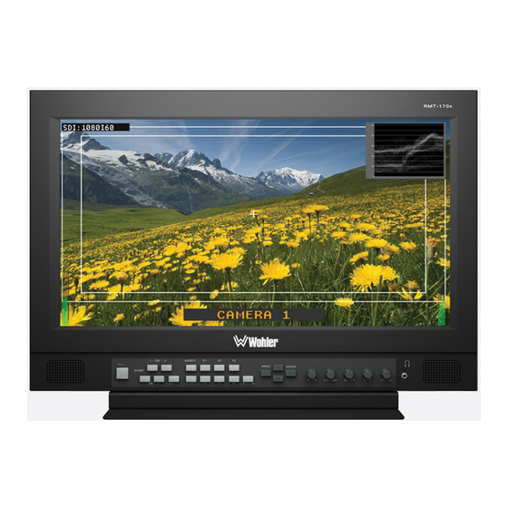
RMT-170e HD Series User Guide Introduction Overview The RMT-170e HD Series monitors are an ideal solution for viewing many different types of HD/SD (up to 1080i and 720p) or analog video and computer input. These monitors come with many in-monitor display features including IMD, tally, time-code, closed captioning, format display, and area/title safe. -
Page 4: Safety Instructions
R M T - 1 7 0 e H D S e r i e s U s e r G u i d e S a f e t y I n s tr u c ti o n s Safety Instructions Read, keep, and follow all of these instructions;... -
Page 5: Accessories
RMT-170e HD Series User Guide A c c e s s o r ie s Accessories Table 1–1 Optional Accessories Part Number Description 790017 Table Top Stand 790018 Rack Ears 790019 Battery Mount (V Type) 790020 Battery Mount (Anton Bauer) Unpacking and Installation Unpack the RMT-170e HD Series monitor and inspect for any apparent physical damage that may have occurred in transit. -
Page 6: Fcc Compliance
R M T - 1 7 0 e H D S e r i e s U s e r G u i d e F C C C o m p l i a n c e Use the included screws to attach either option. The table stand attaches on the rear bottom of the unit and the rack ears attach to the sides. - Page 7 RMT-170e HD Series User Guide F e a t u r e s de-interlacer. Analog signals are internally digitized with a high quality 10-bit over sampled analog to digital converter. Video inputs are provided for serial digital interface (SDI, 2 inputs) and DVI-I digital sources plus VGA (using DVI connector), component (YPrPb), Y/C, and CVBS analog signals.
-
Page 8: Specifications
RMT-170e HD Series monitors. Table 1–2 Monitor Specifications Specifications RMT-170e-SD RMT-170e-HD Power 60 W; 1.5 A; 110 to 240 V AC (50 to 60 Hz) 16.32” W x 12.25” H x 2.83” D Dimensions (Without Stand) (414.5 mm x 311.2 mm x 71.8 mm) - Page 9 S p e ci f i c a t i o n s Table 1–2 Monitor Specifications (Continued) Specifications RMT-170e-SD RMT-170e-HD Viewing Angles 178° H x 178° V Operating Temperature 32° F to 122° F (0° C to 50° C) Figures 1–3...
- Page 10 R M T - 1 7 0 e H D S e r i e s U s e r G u i d e S p e c if i c a ti o n s Input/Output Specifications Table 1–3 Signal Inputs, Frame Rate, and Color Matrix Overscan Native...
- Page 11 — — — All formats marked HD are only supported by the RMT-170e-HD model. The unit supports the input signal 1035I60 but will display in 1080I60 format. The functionality of the front panel buttons varies depending on the input terminal and/or the input signal type. The detailed corresponding relationships are listed in Table 1–5...
- Page 12 R M T - 1 7 0 e H D S e r i e s U s e r G u i d e S p e c if i c a ti o n s Table 1–5 Button/Signal-Terminal Relationships Input Signal Function Video/...
- Page 13 RMT-170e HD Series User Guide S p e ci f i c a t i o n s Table 1–7 Analog Video Input Specifications Parameter Value 75 Impedance Input Level 1 Vp-p nominal Maximum Input Level 2.5 Vp-p centered @ 0V Table 1–8 SDI Video Input Specifications Parameter...
-
Page 14: Front Panel Controls
F r o n t P a n e l C o n t r o l s Front Panel Controls The RMT-170e-HD monitor provides a variety of in monitor data including signal type, waveform/vectorscope, IMD (In-Monitor Display), audio meters, and time code. It also includes a three-color tally light above the display. - Page 15 RMT-170e HD Series User Guide F r o n t P a n e l C o n t r o l s • Audio Levels: Levels for audio channels the are displayed on up to eight meters in pairs, as two or four meters on each side. The A model displays two to four meters.
- Page 16 R M T - 1 7 0 e H D S e r i e s U s e r G u i d e F r o n t P a n e l C o n t r o l s •...
- Page 17 RMT-170e HD Series User Guide F r o n t P a n e l C o n t r o l s Rotary Knob/Indicators The rotary knobs on the right side of the monitor’s control panel have multiple functions most of which are very similar and are listed immediately below: Pushing the knob: Displays the current setting.
-
Page 18: Rear Panel Connectors
R e a r P a n e l C o n n e ct o r s Rear Panel Connectors Figure 1–3 on page 16 illustrates the rear panel connectors. Figure 1–3 RMT-170e-HD Rear Panel Tally Light GPI HD/SD-SDI I/O Configuration RS-485... - Page 19 RMT-170e HD Series User Guide R e a r P a n e l C o n n e c t o r s Table 1–10 GPI/Tally Lamp Color/Pin Designations Tally Lamp Color GPI 1 Pin GPI 2 Pin Green Open Open Orange...
- Page 20 R M T - 1 7 0 e H D S e r i e s U s e r G u i d e R e a r P a n e l C o n n e ct o r s •...
-
Page 21: Using The Osd Menu
RMT-170e HD Series User Guide U s i n g t h e O S D M e n u Using the OSD Menu A description of how to use the follows. Also refer to Table OSD Menu 1–13 below for typical values and domain range. Press the button to display the menu. -
Page 22: Menu Parameters
R M T - 1 7 0 e H D S e r i e s U s e r G u i d e U s in g t h e O SD M e n u Table 1–13 OSD Menu Structure Default Menu... - Page 23 RMT-170e HD Series User Guide U s i n g t h e O S D M e n u Table 1–13 OSD Menu Structure (Continued) Default Menu Parameters Domain Range Value MARKER ENABLE (enabled) or (disabled) Selects the area marker aspect ratio according to the display aspect: •...
- Page 24 R M T - 1 7 0 e H D S e r i e s U s e r G u i d e U s in g t h e O SD M e n u Table 1–13 OSD Menu Structure (Continued) Default Menu...
- Page 25 RMT-170e HD Series User Guide U s i n g t h e O S D M e n u Table 1–13 OSD Menu Structure (Continued) Default Menu Parameters Domain Range Value Selects the audio channel assigned to the specified speaker based on the audio source type, AUD 1L SPEAKER L...
- Page 26 R M T - 1 7 0 e H D S e r i e s U s e r G u i d e U s in g t h e O SD M e n u Table 1–13 OSD Menu Structure (Continued) Default Menu...
- Page 27 RMT-170e HD Series User Guide U s i n g t h e O S D M e n u Table 1–13 OSD Menu Structure (Continued) Default Menu Parameters Domain Range Value Sets the power saving mode (includes backlight and panel power supply, and signal to panel), where: •...
- Page 28 Table 1–13 OSD Menu Structure (Continued) Default Menu Parameters Domain Range Value A user-definable input of up to RMT-170E-HD UMD CHARACTER 16 alphanumeric characters (also includes some symbols) Displays the time code, where: TC DISPLAY • • Displays the waveform: •...
- Page 29 RMT-170e HD Series User Guide U s i n g t h e O S D M e n u Table 1–13 OSD Menu Structure (Continued) Default Menu Parameters Domain Range Value Only available for NTSC (Y/C) signal types: • •...
-
Page 30: Using The Function (F) Keys
R M T - 1 7 0 e H D S e r i e s U s e r G u i d e U s i n g t h e F u n c t i o n ( F ) K e y s Table 1–13 OSD Menu Structure (Continued) Default... - Page 31 RMT-170e HD Series User Guide T e c h n i c a l F u n c t i o n a l O v e r vi e w Figure 1–7 RMT-170e-SD RS-485 (UMD, OSD Tally) RS-485 LED Tally Interface Audio Source...
- Page 32 R M T - 1 7 0 e H D S e r i e s U s e r G u i d e T e c h n i c a l F u n c t i o n a l O v e r v i e w Figure 1–8 RMT-170e-HD RS-485 (UMD, OSD Tally)
Need help?
Do you have a question about the RMT-170e-HD and is the answer not in the manual?
Questions and answers