Advertisement
Quick Links
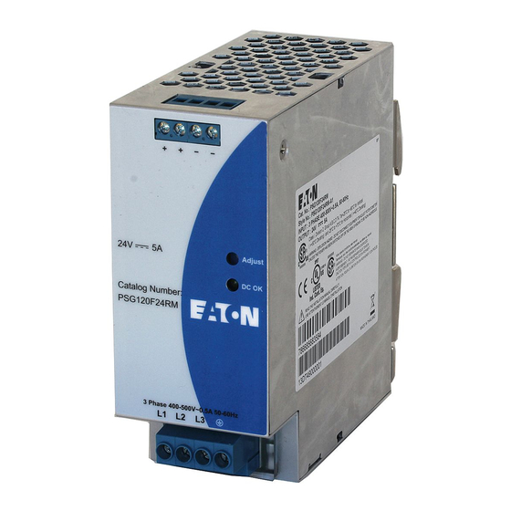
Installation Instructions for PSG120F24RM POWER SUPPLY
READ INSTRUCTIONS BEFORE INSTALLING OR OPERATING THIS DEVICE.
KEEP FOR FUTURE REFERENCE.
(2)
(1)
Figure 1
2
1
3
Figure 2
2
1
Figure 3
7 mm
320-575 VAC absolute*
1
2
Figure 4
Figure 5
Power Derating Curve for PSG in Vertical and Horizontal Position
110
100
90
80
70
60
50
40
30
20
10
0
-25 -20 -15 -10 -5
0
5 10 15 20 25 30 35 40 45 50 55 60 65 70 75 80
Vertical Position
Figure 6
(5)
(3)
(4)
3
L1
DC power in: 450-
800 V to any two
320-575 VAC absolute*
terminals, L1 / L2, or
L2
L1 / L3, or L2 / L3,
non-polarized.
320-575 VAC absolute*
Under Phase Loss
L3
Condition (2-Phase
Input) working
voltage range is
360-575 VAC.
Ambient Temperature (°C)
Horizontal Position
IL125011EN
1. Safety instructions
• Switch main power off before connecting or disconnecting the device. Risk of explosion!
• To guarantee sufficient convection cooling, please keep a distance of 50 mm above and below the
device as well as a lateral distance of 5 mm to other units.
• Note that the enclosure of the device can become very hot depending on the ambient temperature
and load of the power supply. Risk of burns!
• The main power must be turned off before connecting or disconnecting wires to the terminals!
• Do not introduce any objects into the unit!
• Dangerous voltage present for at least 5 minutes after disconnecting all sources of power.
• The power supplies are built-in units and must be installed in a cabinet or room (condensation free
environment and indoor location) that is relatively free of conductive contaminants.
• The unit must be installed in an IP54 enclosure or cabinet in the final installation.
• Warning: Explosion Hazard – Substitution of components may impair suitability for Class I, Division 2.
• Warning: Explosion Hazard – Do not disconnect equipment or adjust potentiometer unless the
power has been switched off or the area is known to be non-hazardous.
CAUTION:
•
"FOR USE IN A CONTROLLED ENVIRONMENT".
2. Device description (Fig. 1)
(1) Input terminal block connector
(2) Output terminal block connector
(3) DC voltage adjustment potentiometer
(4) DC OK control LED (green)
(5) Universal mounting rail system
3. Mounting (Fig. 2)
The power supply unit can be mounting on 35 mm DIN rails in accordance with EN 60715. In Vertical
Position, the device should be installed with input terminal block on the bottom. In Horizontal Position, the
device should be installed with input terminal block on the left side.
Each device is delivered ready to install.
Snap on the DIN rail as shown in Fig. 2:
1. Tilt the unit slightly upwards and put it onto the DIN rail.
2. Push downwards until stopped.
3. Press against the bottom front side for locking.
4. Shake the unit slightly to ensure that it is secured.
4. Dismounting (Fig. 3)
To uninstall, pull or slide down the latch as shown in Fig. 3. Then, slide the PSU in the opposite direction,
release the latch and pull out the PSU from the rail.
5. Connection
The terminal block connectors allow easy and fast wiring.
You can use flexible (stranded wire) or solid cables with cross sections:
Stranded / Solid
Table
(mm²)
(AWG)
(1)
0.82-3.3
18-12
(2)
0.82-3.3
18-12
To secure reliable and shock proof connections, the stripping length should be 7 mm (see Fig. 4 (1)).
Please ensure that wires are fully inserted into the connecting terminals as shown in Fig. 4 (2).
In accordance to EN 60950 / UL 60950, flexible cables require ferrules.
Use appropriate copper cables that are designed to sustain operating temperature of:
1. 60°C, 60°C / 75°C for USA
2. At least 75°C for ambient not exceeding 50°C, and 90°C for ambient exceeding 50°C for Canada.
5.1. Input connection (Fig. 1, Fig. 5)
Use L1, L2, L3 and PE connections of input terminal connector to establish the 3 x 400-500 VAC
connection. Fig. 5 shows the connection to the various network types.
In the event of a phase failure, unrestricted operation is possible with nominal capacity.
The unit is protected with internal fuse (not replaceable) at L pin and it has been tested and approved on
20A (UL) and 16A (IEC) branch circuits without additional protection device. An external protection device
is only required if the supplying branch has an ampacity greater than above. Thus, if an external protective
device is necessary, or, utilized, a minimum value of 13A B- or 6A C- characteristic breaker should be
used.
The internal fuse must not be replaced by the user.
In case of internal defect, please call 1 - 877 - ETN - CARE
5.2. Output connection (Fig. 1 (2))
Use the "+" and "-" screw connections to establish the 24Vdc connection. The output provides 24 VDC.
The output voltage can be adjusted from 24 to 28 VDC on the potentiometer. The green LED DC OK
displays correct function of the output (Fig. 1 (4)). The device has a short circuit and overload protection
and an overvoltage protection limited to 35 VDC.
5.3. Output characteristic curve
The device functions normal under operating line and load conditions. In the event of a short circuit or
overload the output voltage and current collapses (I
reduced and bounces until short circuit or overload on the secondary side has been removed.
5.4. Thermal behavior (Fig. 6).
In the case of ambient temperatures above +50°C (Vertical) or +40°C (Horizontal), the output capacity has
to be reduced by 2.5% per degree Celsius increase in temperature, and at +70°C to +80°C (Vertical) or
+60°C to +70°C (Horizontal), the output capacity has to be reduced by 5% per degree Celsius increase in
temperature. If the output capacity is not reduced when T
device will run into thermal protection by switching off i.e. device will go in bouncing mode and will recover
when ambient temperature is lowered or load is reduced as far as necessary to keep device in working
condition.
FOR TECHNICAL ASSISTANCE CALL 1 - 877 - ETN - CARE
US: Eaton
W126N7250 Flint Drive
Menomonee Falls, WI 53051
www.eaton.com
EU: Eaton Industries GmbH
Hein-Moeller-Str. 7-11
53115 Bonn, Germany
www.eaton.eu
Torque
(Kgf-cm)
(lb in)
9.3
8.1
6.2
5.4
or I
is >I
(150%)). The secondary voltage is
O/L
S/C
surge
> 50°C (Vertical) or > 40°C (Horizontal), the
Amb
Rev. 05
Advertisement

Subscribe to Our Youtube Channel
Related Manuals for Eaton PSG120F24RM


Summary of Contents for Eaton PSG120F24RM
- Page 1 US: Eaton W126N7250 Flint Drive IL125011EN Menomonee Falls, WI 53051 www.eaton.com Installation Instructions for PSG120F24RM POWER SUPPLY EU: Eaton Industries GmbH Hein-Moeller-Str. 7-11 READ INSTRUCTIONS BEFORE INSTALLING OR OPERATING THIS DEVICE. 53115 Bonn, Germany KEEP FOR FUTURE REFERENCE. www.eaton.eu 1. Safety instructions •...
- Page 2 1.5 kVAC Protection degree IP20 Safety class Class I with PE connection Eaton Industries GmbH Contact your regional Eaton office for additional technical support Hein-Moeller-Strabe 7-11, 53115 Bonn, Germany Eaton.com/recycling Americas Europe – Middle East – Africa – Asia Pacific...
Need help?
Do you have a question about the PSG120F24RM and is the answer not in the manual?
Questions and answers