Table of Contents
Advertisement
Quick Links
I.L. 70C1080H01
Instructions for Field Installing
Ground Fault Alarm/Power Supply Modules
into Digitrip 520M Equipped Cutler Hammer
Magnum and Magnum DS Circuit Breakers
Table of Contents
1.0 General Description ................................................ 2
1.1
Auxiliary Power & Ground Alarm .................. 2
1.2
Ground Fault Trip ......................................... 2
1.3
Ground Fault Alarm ...................................... 2
2.0 Choosing the Proper Upgrade Kit ........................... 2
3.0 Hardware Supplied with Upgrade Kit ...................... 3
4.0 Tools Required ....................................................... 3
5.0 Installation Preparation ........................................... 3
5.1
Remove Breaker From Line ......................... 3
5.2
Manually Tripping the Breaker ...................... 3
6.0 Installation Procedure ............................................. 3
6.1
Removing the Front Cover ........................... 3
6.2
Removing the Rating Plug ............................ 3
6.3
Removing the Trip Unit ................................ 4
6.4
Removing the Trip Deck Plate ...................... 4
7.0 Mounting the Module .............................................. 5
8.0 Wiring Harnesses ................................................... 5
8.1
Preparing the Harness ................................. 5
8.2
Running the Harness ................................... 5
8.3
Attaching Harnesses to Module ................... 5
8.4
9.0 Reassembly ............................................................ 6
9.1
Replacing the Trip Deck ............................... 6
9.2
Reinstalling the Trip Unit .............................. 6
9.3
Reinserting the Rating Plug .......................... 7
9.4
Final Internal Visual Inspection ..................... 7
9.5
Replacing the Front Cover ........................... 7
10.0 Post Installation Testing .......................................... 7
10.1 When to Test ................................................ 7
10.2 Code Requirements ..................................... 8
10.3 Standards Requirements ............................. 8
10.4 Test Methods ............................................... 8
10.4.1 Power Up Check ............................... 8
10.4.2 Secondary Injection Test ................... 8
10.4.3 Primary Injection Test ........................ 8
Effective 9/21/99
10.4.4 General Test Instructions For
Secondary and Primary Injection
Methods ....................................................... 8
10.4.5 Cutler-Hammer Test Kit Check .......... 9
11.0 Standards ............................................................. 10
12.0 Disclaimers ........................................................... 10
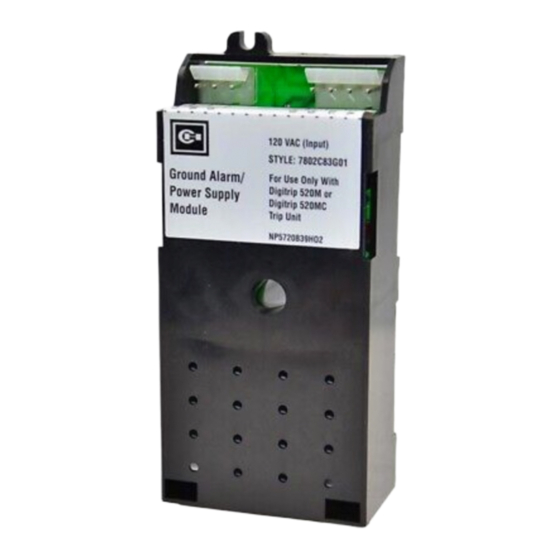
Figure 1.1 Ground Alarm / Power Supply Module
(Style # 7802C83G01 shown)
I.L. 70C1080H01
Page 1
Advertisement
Table of Contents

Related Manuals for Eaton Cutler-Hammer 7802C83G01


Summary of Contents for Eaton Cutler-Hammer 7802C83G01
-
Page 1: Table Of Contents
I.L. 70C1080H01 I.L. 70C1080H01 Page 1 Instructions for Field Installing Ground Fault Alarm/Power Supply Modules into Digitrip 520M Equipped Cutler Hammer Magnum and Magnum DS Circuit Breakers Table of Contents 1.0 General Description ..........2 10.4.4 General Test Instructions For Auxiliary Power &... -
Page 2: General Description
I.L. 70C1080H01 Page 2 NOTE: The recommendations and information contained Only LED on the front of the trip unit will indicate the herein are based on experience and judgement, but presence of a ground fault condition that exceeds the should not be considered to be all inclusive or to cover programmed setting every application or circumstance which may arise. -
Page 3: Hardware Supplied With Upgrade Kit
I.L. 70C1080H01 Page 3 5.2 Manually Tripping the Breaker 3.0 Hardware Supplied with Upgrade Kit Each Cutler-Hammer Field Installable Kit for Ground Before installing the Ground Alarm / Power Supply Alarm / Power Supply module for Magnum DS Breaker module, manually force the isolated breaker to trip via the with Digitrip 520M comes with the following: push buttons on the front panel. -
Page 4: Removing The Trip Unit
I.L. 70C1080H01 Page 4 6.3 Removing the Trip Unit To remove the trip unit from the circuit breaker, deflect the spring clip underneath the trip unit with a screwdriver. When unlocked, you will be able to pull the trip unit straight out and, by doing so, will disengage the trip unit’s printed circuit board connectors K1 &... -
Page 5: Mounting The Module
I.L. 70C1080H01 Page 5 factory. The second is supplied with the field installable upgrade kit. It comes ready to install with a four conductor connector on one side and male pins on the other which are inserted into the Secondary Block “A” which is a black connector on the top left side of the breaker. -
Page 6: Reassembly
I.L. 70C1080H01 Page 6 of the breaker (Figure 8.1). The wires are marked A-10, two lower partially loosened attachment screws. Tuck all A-11, A-14 and A15. According to the label on the block, wiring bundles neatly behind it. Position the mounting tabs insert them into the proper terminal slots. -
Page 7: Reinserting The Rating Plug
I.L. 70C1080H01 Page 7 CAUTION BEFORE YOU FIT THE RATING PLUG INTO THE TRIP UNIT, BE SURE TO CHECK THAT THE SENSOR RATING MATCHES THAT PRINTED ON THE RATING PLUG DOOR. INSTALLING A RATING PLUG THAT DOES NOT MATCH THE SENSOR RATING CAN PRODUCE SERIOUS MIS-COORDINATION AND/OR FAILURE OF THE PROTECTION SYSTEM. -
Page 8: Code Requirements
I.L. 70C1080H01 Page 8 If the Digitrip does NOT have a ground element and the CAUTION module was installed just for the powering of the LED display, then perform an overload test at 200% to verify tripping. This would complete the verification sequence. If TESTING A CIRCUIT BREAKER WHILE IT IS IN- a ground element IS involved, continue with the following SERVICE AND CARRYING LOAD CURRENT IS NOT... - Page 9 I.L. 70C1080H01 Page 9 WARNING PERSONAL INJURY CAN OCCUR WHEN WORKING ON POWER SYSTEMS. ALWAYS TURN OFF POWER SUPPLYING BREAKER BEFORE CONDUCTING TESTS. TEST OUT OF THE CELL, IF POSSIBLE. THERE IS A HAZARD OF ELECTRICAL SHOCK OR BURN WHENEVER WORKING IN OR AROUND ELEC- TRICAL EQUIPMENT.
- Page 10 I.L. 70C1080H01 Page 10 12.0 DISCLAIMERS CAUTION This instruction booklet is published solely for information purposes and should not be considered all inclusive. If BEFORE PLUGGING A TEST KIT INTO THE TEST further information is required, consult Cutler-Hammer, PORT, PLACE THE LTM JUMPER IN THE INACTIVE Inc.
- Page 11 I.L. 70C1080H01 Page 11 Cutler-Hammer Pittsburgh, PA U.S.A. Effective 9/21/99 Printed in U.S.A. Effective 9/21/99...
Need help?
Do you have a question about the Cutler-Hammer 7802C83G01 and is the answer not in the manual?
Questions and answers