
Related Manuals for Eaton MFD-AC-CP4


Summary of Contents for Eaton MFD-AC-CP4
- Page 1 09/10 MN05013011Z-EN User Manual replaces 10/04 AWB2528-1548GB MFD-AC-CP4, MFD-CP4, MFD-80 Power Supply/Communication Module...
- Page 2 2008, edition date 02/08 edition 2010, edition date 09/10 See revision protocol in the “About this manual“ chapter © 2002 by Eaton Industries GmbH, 53105 Bonn Production: Thomas Kracht Translation: Terence Osborn All rights reserved, including those of the translation.
- Page 3 Danger! Dangerous electrical voltage! Before commencing the installation • Disconnect the power supply of the device. • Suitable safety hardware and software measures should be implemented for the • Ensure that devices cannot be accidentally I/O interface so that a line or wire breakage restarted.
- Page 4 • Measures should be taken to ensure the • Wherever faults in the automation system proper restart of programs interrupted may cause damage to persons or property, after a voltage dip or failure. This should external measures must be implemented to not cause dangerous operating states even ensure a safe operating state in the event for a short time.
-
Page 5: Table Of Contents
09/10 MN05013011Z-EN Contents About This Manual List of revisions Target group Other manuals Writing Conventions Device designation About the Display/Operator System Components of the display/operator system Proper use System overview – Display/keypad – Power supply unit/communication module Device application Connecting the display/operator system with a single device Connecting display/operator system with easyNet station... - Page 6 – MFD-80-XS protective cover – MFD-CP4Power supply/communication module Technical data – General ambient conditions – MFD-80.. display/operating unit – MFD-XM-80 protective diaphragm – MFD-XS-80 protective cover – MFD-..-CP4 power supply unit/communication module – MFD-AC-CP4… power supply unit/communication module Alphabetical index...
-
Page 7: About This Manual
This 02/08 edition has been completely revised compared to the previous edition of 10/04. This edition now also covers the easySafetycontrol relay. The 09/10 edition has been changed to include the Eaton designations. Target group This display/operator device must only be mounted and connected by qualified electrical personnel or a person familiar with the electrical installation. -
Page 8: Writing Conventions
Device designation The following short names for equipment types are used in this manual, as far as the description applies to all of these types: • MFD-…-CP4 for – MFD-AC-CP4 – MFD-CP4 • MFD-…-CP4-500 for – MFD-AC-CP4-500 – MFD-CP4-500 • MFD-…-CP4-800 for –... -
Page 9: About The Display/Operator System
09/10 MN05013011Z-EN About the Display/Operator System Components of the The display/operator system described here consists of the display/operator system MFD-CP4 power supply/communication module, the MFD-80.. display/operator unit and the MFD-CP4-...-CAB connecting cable. The following tables shows the individual components of the display/operator system with their type designations. -
Page 10: System Overview
09/10 MN05013011Z-EN About the Display/Operator System System overview Figure 1: System overview ( Legend a page 7) -
Page 11: Display/Keypad
09/10 MN05013011Z-EN System overview Legends to Figure1: a easy500 basic units b easy700 basic units c MFD80-B/MFD-80 multi-function display d Power supply unit/communication module with MFD-..-CP4-500 (above) or MFD-..-CP4-800 (below) connecting cable e easy800 basic units The display/operator system consists of the power supply unit/communication module and the display/operator unit. -
Page 12: Power Supply Unit/Communication Module
09/10 MN05013011Z-EN About the Display/Operator System Key to part numbers MFD - 80 - B B = with buttons with display Multi-function display Power supply unit/communication module Figure 3: Power supply unit/communication module a Supply voltage b Serial interface for point-to-point connection Key to part numbers MFD - CP4 - XXX 500 = For connection to easy500 and easy700... -
Page 13: Device Application
09/10 MN05013011Z-EN Device application The display/operator system enables you to externally carry out the same display/operator functions of an easy500, easy700, easy800, easySafety or an MFD (MFD…CP8/CP10 or MFD…CP8/CP10 with MFD-80-B). If, for example, one of the devices is fitted in the control cabinet, the display/oper- ator unit can be installed in the control cabinet door to provide display and operator functions. -
Page 14: Connecting Display/Operator System With Easynet Station
09/10 MN05013011Z-EN Device application Connecting display/oper- The display/operator system enables you to access all ator system with easyNet stations via the easyNet, apart from easySafety devices. station To do this connect the display/operator system to a station and select the station on the display/operator system via <COM ->... -
Page 15: Connection Faulty
09/10 MN05013011Z-EN Connecting the display/oper- ator system with a single device easy800 (NET-ID 1) MFD-...-NT easySafety (NET-ID 6) easySafety MFD-...-NT easy800 MFD-80-B MFD-CP4... easySoft-Pro easySoft-Safety Figure 5: Access options in terminal mode (see also Table 2) a Terminal Mode Connection faulty If the connection between the display/operator system and Connection the station is faulty or interrupted, the display/operator... -
Page 16: Graphic Mode On The Remotely Operated Mfd
09/10 MN05013011Z-EN Device application Graphic mode on the If you connect a display/operator system with an MFD remotely operated MFD (MFD-80-B with MFD…CP8/CP10) in graphic mode, the following display is shown on the display/operator system: The remote device is in Graphic mode You can terminate graphic mode from the display/operator system by pressing ALT + ESC. -
Page 17: Installation
09/10 MN05013011Z-EN Installation The MFD-CP4 must only be installed and connected up by trained electricians or a person familiar with the installation of electrical equipment. The MFD-CP4 is installed in the following order: • Mounting, • Connecting the serial interface, •... -
Page 18: Fitting The Protective Diaphragm
09/10 MN05013011Z-EN Installation Fitting the protective diaphragm For special applications such as in the food industry, the keypad must be protected against the ingress of dust, liquids etc. In this case fit the protective diaphragm over the display/ operating unit. Fit the protective diaphragm before mounting the display/ operating unit. -
Page 19: Mounting The Protective Cover
09/10 MN05013011Z-EN Mounting Figure 8: Correct location of the protective diaphragm If the protective diaphragm has to be replaced, the display/operating unit has to be removed. Replace the diaphragm and refit the device. Mounting the protective cover The protective cover is provided for using the device in aggressive environments. - Page 20 09/10 MN05013011Z-EN Installation First remove the front frame before mounting. Figure 9: Removing the front frame The protective cover can be mounted in two different posi- tions. Choose the position that is most suitable for the applica- tion at hand and your requirements. Figure 10: Position of the protective cover...
- Page 21 09/10 MN05013011Z-EN Mounting Mount the protective cover as shown in the figure. Figure 11: Mounting the protective cover Sealing the protective cover Figure 12: Sealing the protective cover The grip handle of the protective cover is provided with holes that can be used in any mounting position. You can fit a wire or similar material through these holes in order to seal the cover.
-
Page 22: Mounting The Display/Operating Unit (Front Mounting)
09/10 MN05013011Z-EN Installation Mounting the display/operating unit (front mounting) The protective diaphragm or the protective cover must be fitted beforehand. Drill and punch out two 22.5 mm diameter holes in the front plate. The diameter is the same as is normally required for control circuit devices. - Page 23 09/10 MN05013011Z-EN Mounting Fit the display/operator unit in the punched fixing holes. Figure 14: Mounting the display/operator unit Tighten the display/operating unit with the M22-MS mounting ring tool (a figure 15). The tightening torque must be between 1.2 and 2 Nm Ensure that the correct torque is used.
-
Page 24: Removing The Display/Operating Unit (Front Mounting)
09/10 MN05013011Z-EN Installation Figure 15: Screw fastening the display/operating unit Figure 16: Rear of the mounted display/operator unit Removing the display/operating unit (front mounting) Unscrew the fixing element and remove the display/oper- ator unit. -
Page 25: Mount Power Supply Unit/Communication Module
09/10 MN05013011Z-EN Mounting Mount power supply unit/communication module Figure 17: Mount power supply unit/communication module... -
Page 26: Removing The Power Supply/Communication Module
09/10 MN05013011Z-EN Installation Removing the power supply/communication module Use a screwdriver with a 3.5 x 0.6 mm slot width. Insert the screwdriver into the strap of the fixing shaft catch. Lever out the slide catch. Pull out the power supply/CPU module from the fixing shafts. -
Page 27: Connecting The Power Supply
09/10 MN05013011Z-EN Connections Connecting the power supply The required connection data for the MFD-CP4 is provided in the Section “Technical data”, page 39. Power supply MFD-CP4/MFD-AC-CP4 L01+ L02+ L01– > 1 A > 1 A U e = 24 V H U e = 230 V h (20.4 –... -
Page 28: Connecting Cable
09/10 MN05013011Z-EN Installation Connecting cable The MFD-CP4 is provided with a serial interface. The easy500, easy700, easy800, easySafety or MFD-CP8/ CP10… can be connected to this interface. Selecting connection cables Different connecting cables are required depending on which device is connected to the MFD-..-CP4: Table 3: Selecting connection cables MFD-..-CP4 connected to ... - Page 29 09/10 MN05013011Z-EN Connections Connecting the connection cable Remove the interface cover carefully Use a screwdriver to press down the recess next to the terminal and connect the wires of the connection cable to the terminals in the order stated . Proceed accordingly in the reverse order to remove the connection cable Refit the interface cover...
- Page 30 09/10 MN05013011Z-EN Installation Figure 20: Connecting the connection cable X1 = grey, X2 = brown, X3 = yellow, X4 = white, X5 = green Fit the connection cable plug into the easy basic device. Figure 21: Fitting the connection plug a to the easy basic unit Left: easy800, easySafety (analog at MFD) Right: easy500, easy700...
-
Page 31: Commissioning
09/10 MN05013011Z-EN Commissioning Switch-on Before switching on check that the power supply and the connection cable are properly connected: – Terminal +24 V: Voltage +24 V – Terminal 0 V: Voltage 0 V Warning! The station connected with the display/operator system may be far or invisible from your actual location. - Page 32 09/10 MN05013011Z-EN Commissioning As soon as you connect the display/operator system to the Connection device (e.g. easy800 or easySafety) via a connection cable establishme and switch it on, it will try to establish a connection to this in progress... connected device, due to the preset NET-ID. If the connected device is a single device, a 0 must be entered in the display/operator system as the station ID.
-
Page 33: Setting The Properties Of The Display/Operator System
09/10 MN05013011Z-EN Setting the properties of the display/operator system Operating buttons The buttons of the display/operating unit have the following functions: Move to next menu level Call menu item Activate, change, store entries Move to previous menu level Cancel entries since last OK Í... -
Page 34: Terminal/Local Mode
09/10 MN05013011Z-EN Setting the properties of the display/operator system Terminal/local mode You can choose between Terminal and Local modes: In Terminal mode, the display/operator system communi- cates with the connected device, e.g. easy800. The display and button functions of the easy800 are taken over by the display/operator system. -
Page 35: Terminal/Local Mode Overview
09/10 MN05013011Z-EN Operating buttons Terminal/local mode overview The following overview shows the menu structure and the operation for selecting the parameters. In Terminal mode, the display of an easy800 was selected as an example. Terminal mode display Connection establishment I .2..5..in progress... - Page 36 09/10 MN05013011Z-EN Setting the properties of the display/operator system Local mode (main menu) Current STATION ID: COM... selection BAUDRATE: 9600B MENU LANGUAGE... flashes in LIGHTING: menu CONTRAST : +2 Cursor Í Ú ENGLISH COM... DEUTSCH MENU LANGUAGE... FRANCAIS LIGHTING: ESPANOL CONTRAST : +2 ITALIANO...
-
Page 37: Settings In Local Mode
09/10 MN05013011Z-EN Operating buttons Settings in local mode Station ID selection If the main menu of the display/operator system is not active, COM... press the “*” button to enter the menu. MENU LANGUAGE... LIGHTING: 60% Select the COM menu item and press the OK button. CONTRAST: +2 The Station ID menu will appear. -
Page 38: Setting The Menu Language
09/10 MN05013011Z-EN Setting the properties of the display/operator system Setting the menu language If the main menu of the display/operator system is not active, press the “*” button to enter the menu. Use the Í and Ú buttons to select the Menu language COM... -
Page 39: Changing The Light
09/10 MN05013011Z-EN Operating buttons Changing the light If the main menu of the display/operator system is not active, press the “*” button to enter the menu. Use the Í and Ú buttons to select the Lighting menu COM... item. MENU LANGUAGE... LIGHTING: 60% The cursor moves to the percentage value of the lighting. -
Page 40: Changing The Contrast
09/10 MN05013011Z-EN Setting the properties of the display/operator system Changing the contrast If the main menu of the display/operator system is not active, press the “*” button to enter the menu. Use the Í and Ú buttons to select the Contrast menu COM... -
Page 41: Appendix
09/10 MN05013011Z-EN Appendix Dimensions MFD-80.. display/operating unit 28.25 28.25 13.7 g0.2 86.5 MFD-80-XM protective diaphragm 22.5 88.5... -
Page 42: Mfd-80-Xs Protective Cover
09/10 MN05013011Z-EN Appendix MFD-80-XS protective cover 86.5 MFD-CP4Power supply/communication module 22.5 22.5 36.2... -
Page 43: Technical Data
09/10 MN05013011Z-EN Dimensions Technical data General ambient conditions Climatic conditions (damp heat constant to IEC 60068-2-78; cyclical to IEC 60068-2-30) (cold to IEC 60068-2-1, heat to IEC 60068-2-2) Operating ambient temperature °C, (°F) –25 to 55, (–13 to 131) Installed horizontally/vertically Condensation Prevent condensation by means of suitable measures... - Page 44 09/10 MN05013011Z-EN Appendix Electromagnetic compatibility (EMC) Electrostatic discharge (ESD), (IEC/EN 61000-4-2, severity level 3) Air discharge Contact discharge Electromagnetic fields (RFI), (IEC/EN 61000-4-3) Radio interference suppression (EN 55011, EN 55022), limit class Fast transient burst (IEC/EN 61000-4-4, severity level 3) Supply cables Signal cables High energy pulses (Surge) MFD (IEC/EN 61000-4-5,...
-
Page 45: Mfd-80
09/10 MN05013011Z-EN Dimensions MFD-80.. display/operating unit Front dimensions W x H x D With buttons 86.5 x 86.5 x 21.5 inches 3.41 x 3.41 x 0.85 Without buttons 86.5 x 86.5 x 20 inches 3.41 x 3.41 x 0.79 Overall dimensions with fixing shaft W x H x D With buttons 86.5 x 86.5 x 43 inches... -
Page 46: Mfd-Xm-80 Protective Diaphragm
09/10 MN05013011Z-EN Appendix Operator buttons Number Pushbutton illumination (LED) Number Color green MFD-XM-80 protective diaphragm Dimensions B x H x T 88 x 88 x 25 inches 3.46 x 3.46 x 0.98 Weight 0.055 Mounting Is fitted over the display/function keys (with silver bezel) MFD-XS-80 protective cover Dimensions B x H x T... -
Page 47: Mfd
09/10 MN05013011Z-EN Dimensions MFD-..-CP4 power supply unit/communication module Dimensions B x H x T 75 x 58 x 36.2 inches 2.95 x 2.28 x 1.43 Weight 0.362 Mounting Plug-fitted to the display fixing shaft Current supply Rated voltage Nominal value V DC, 24, (+20, –15) Permissible range... -
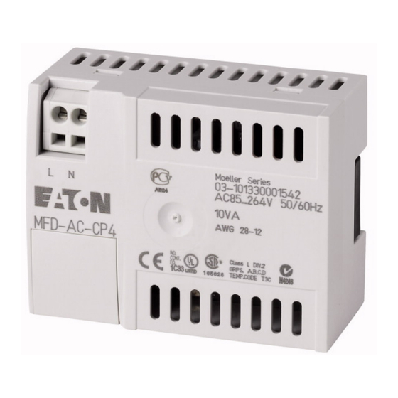
Page 48: Mfd-Ac-Cp4
09/10 MN05013011Z-EN MFD-AC-CP4… power supply unit/communication module Dimensions B x H x T 107.5 x 90 x 30 Weight 0.14 Mounting Fitted on the fixing shaft of the display or on top-hat rail accor- ding to IEC/EN 60715, 35 mm deep (without... -
Page 49: Alphabetical Index
09/10 MN05013011Z-EN Alphabetical index Area of application ..........5 Baud rate Menu structure ..........32 Baud rate adjustment ........28, 33 Cable protection ..........23 Commissioning ............27 Connecting cable ............24 plug .............26 Connecting display/operator system with easyNet stations ...........10 Connecting the display/operator system with a single device ..........9 Connection Connecting cable ..........24... - Page 50 09/10 MN05013011Z-EN Alphabetical index easyNet operation ..........10 EMC ..............40 Environmental Conditions ........39 Illumination ............35 Installation -> Mounting Insulation resistance ..........40 Keypad Functions .............29 Position on the device ........7 Language setting ..........27 Local mode Switching to Terminal mode ......30 Menu language ...........27 Setting ............34 Minimum clearances when mounting in a control panel ..........13...
- Page 51 09/10 MN05013011Z-EN Alphabetical index Polarity ..............23 Power supply Technical data ........43, 44 Power supply unit/communication module Dimensions ..........38 Mounting .............21 Technical data ..........43 Protection against polarity reversal ......23 Protective cover Dimensions ..........38 Mounting .............15 Sealing ............17 Technical data ..........42 Protective diaphragm Mounting .............14 Technical data ..........42 Sealing the protective cover .........17...
- Page 52 09/10 MN05013011Z-EN Technical data .............39 Terminal Mode ..........10, 27 Terminal mode Switching to Local mode ......30 Terminating graphic mode (on remotely controlled MFD) ..............36 Tools ..............40 Type code Display/operator unit ........8 Power supply unit/communication module ..8 User language .............27...
Need help?
Do you have a question about the MFD-AC-CP4 and is the answer not in the manual?
Questions and answers