Table of Contents
Advertisement
Quick Links
Installation Instructions for PSG120E POWER SUPPLY
READ INSTRUCTIONS BEFORE INSTALLING OR OPERATING THIS DEVICE. KEEP FOR FUTURE REFERENCE.
(2)
(1)
Figure 1
Figure 2
Figure 3
Figure 4
Figure 5
Figure 6
(3)
(5)
(4)
85 – 264 Vac absolute or
120 – 375 Vdc absolute
non-polarized
1. Safety instructions
• Switch main power off and wait 5 minutes before making any connection or
disconnection on the device. Danger of explosion!
• Dangerous voltage present for at least 5 minutes after disconnecting all sources of
power.
• For sufficient convection cooling keep a distance of 50 mm above and below the
device as well as a lateral distance of 20 mm to other units.
• The enclosure of the device can become very hot depending on the ambient
temperature and load of the power supply. Risk of burns!
• Do not introduce any objects into the unit!
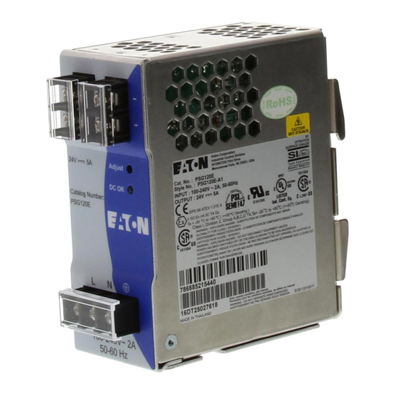
2. Device description (Fig. 1)
(1) Input terminal block connector
(2) Output terminal block connector
(3) DC voltage adjustment potentiometer
(4) DC OK control LED (green)
(5) Universal mounting rail system
3. Mounting (Fig. 2)
The power supply unit can be mounted on 35 mm DIN rails in accordance with EN 60715.
The device should be installed horizontally with input terminal blocks on the bottom.
Each device is delivered ready to install.
Snap on the DIN rail as shown in Fig. 2:
1. Tilt the unit slightly upwards and put it onto the DIN rail.
2. Push downwards until stopped.
3. Press against the bottom front side for locking.
4. Shake the unit slightly to ensure that it is secured.
4. Removal (Fig. 3)
To uninstall, pull or slide down the latch as shown in Fig. 3. Then, slide the PSU in the
opposite direction, release the latch and pull out the PSU from the rail.
5. Connection
The terminal block connectors allow easy and fast wiring. A plastic cover provides the
necessary isolation of the electric connection.
Use flexible (stranded wire) or solid cables 0.32-2.1 mm² (AWG 22-14) and torque of 0.78-
0.98 Nm (6.94-8.68 lb in). The insulation stripping length should be 7 mm
In accordance to EN 60950 / UL 60950, flexible cables require ferrules.
Use copper wire that is designed to sustain operating temperature of
75°C or more to fulfill UL requirements.
For stranded wires it is recommended to use suitable lug to crimp wires
(See Fig. 4).
5.1. Input connection (Fig. 1and Fig. 5)
Refer to Figure 5 for input connections.
The device has an internal fuse. 6 A, 10 A or 16 A power circuit breakers are recommended
as backup fuses.
The internal fuse must not be replaced by the user.
In case of internal defect, Please call 1- 877- ETN - CARE
5.2. Output connection (Fig. 1 (2))
Use the "+" and "-" screw connections to establish the 24 VDC connection. The output
provides 24 VDC. The output voltage can be adjusted from 22 to 28 VDC on the
potentiometer. The green LED DC OK displays correct function of the output (Fig. 1 (4)).
The device has a short circuit and overload protection and an over voltage protection limited
to 35 VDC.
5.3. Output characteristic curve
The device functions normal under operating line and load conditions. In the event of a
short circuit or over load the output voltage and current collapses (I
(150%)). The secondary voltage is reduced and bounces/oscillates until short circuit or over
load on the secondary side has been removed.
5.4. Thermal behavior (Fig. 6)
In the case of ambient temperatures above +50°C, the output capacity has to be reduced
by 2.5% per increase in temperature. If the output capacity is not reduced when T
50 °C device will run into thermal protection by switching off i.e. device will go in
bouncing/oscillates mode and will recover when ambient temperature is lowered or load is
reduced as far as necessary to keep device in working condition.
FOR TECHNICAL ASSISTANCE CALL 1 - 877- ETN – CARE
IL00912002E
or I
is > I
O/L
S/C
surge
>
Amb
Advertisement
Table of Contents

Subscribe to Our Youtube Channel
Related Manuals for Eaton PSG120E


Summary of Contents for Eaton PSG120E
- Page 1 IL00912002E Installation Instructions for PSG120E POWER SUPPLY READ INSTRUCTIONS BEFORE INSTALLING OR OPERATING THIS DEVICE. KEEP FOR FUTURE REFERENCE. 1. Safety instructions • Switch main power off and wait 5 minutes before making any connection or disconnection on the device. Danger of explosion! •...
- Page 2 IL00912002E TECHNICAL DATA FOR PSG120E Input (AC) Nominal input voltage 100-240 VAC Voltage range 85-264 VAC (DC input range 120-375 VDC) Frequency 47-63 Hz (0 Hz @ DC input) Nominal current 1.4 A @ 115 VAC, 0.8 A @ 230 VAC Inrush current limitation.
Need help?
Do you have a question about the PSG120E and is the answer not in the manual?
Questions and answers