
Related Manuals for Growatt Smart Meter-US


Summary of Contents for Growatt Smart Meter-US
- Page 1 SM-US-200 Electricity Meter & Installation Guide V1.0 Growatt New Energy Growatt USA,Inc 9227 Reseda Blvd,#435 Northridge,CA 91324,USA. +818 800-9177 usaservice@ginverter.com www.growatt-america.com...
- Page 2 Contents IMPORTANT SAFETY INSTRUCTIONS IMPORTANT SAFETY INSTRUCTIONS SAVE THESE INSTRUCTIONS 1 Introduction This manual contains important instructions for Model SM-US-200 that shall be followed during installation and maintenance of the inverter. 2 Meter Installation Risk of electrical shock 2.1 Installation Guidelines Risque d'électrocution 2.2 Installing and Connecting the Meter Wait for 5minutes before engaging in the indicated action...
- Page 3 1 Introduction Meter Installation 2 In a single inverter system, the meter is connected directly to the inverter. If your inverter While Installing the meter, the National Electrical Code, ANSI/NFPA 70 and Canadian has a built-in revenue grade meter (RGM; the inverter is referred to a revenue grade Electrical Code C22.1.
- Page 4 1.Verify that power is OFF before making connections. 2.Insert a grounding cable through the appropriate conduit and the knockout that was opened and connect it from Pin 5 of the 5-pin terminal block to the grounding terminal 3.Connect the AC side wires (meter input) using the 5-pin terminal block: Insert the wires through the appropriate conduit and the knockout that was opened.
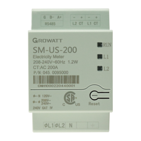
- Page 5 3 Panel introduction Meter Technical Specifications 4 3.1 Meter Status Leds Meter Electrical Service Units The three status LEDs on the front of the meter can help indicate correct measurements SM-US-200 and operation. At normal startup - when power is first applied, all the LEDs light up sequentially for 1 Rated Voltage-Line to N sec.
- Page 6 5 Dimensions 5.1 Meter Dimensions(±0.5mm) Fig 5.1 5.2 Current Transformers Dimensions(±0.5mm) 5 4 . 8 51 . 9 4 6 .5 23 . 0 2 3.0 70. 5 39 . 0 Fig 5.2 APPENDIX Accessories list Item Quantity Current Transformer Plug component Specification Revision 1.0 Contents subject to change with notice to contract customers.
Need help?
Do you have a question about the Smart Meter-US and is the answer not in the manual?
Questions and answers