Table of Contents
Advertisement
Quick Links
Advertisement
Table of Contents
Troubleshooting

Related Manuals for Siemens SITRANS RD200


Summary of Contents for Siemens SITRANS RD200
- Page 1 Communications and Displays SITRANS RD200 Operating Instructions 11/2012 SITRANS...
- Page 2 The user is responsible for all changes and repairs made to the device by the user or the user’s agent. All new components are to be provided by Siemens Milltronics Process Instruments. Restrict repair to faulty components only.
-
Page 3: Table Of Contents
Table of Contents SITRANS RD200 .........................1 SITRANS RD200 ............................1 Safety Notes ............................1 The Manual ............................2 Specifications ........................3 Power............................. 3 Mounting ............................3 Memory ............................4 Programming..........................4 Display ............................4 Outputs............................4 Serial Communications......................5 Inputs.............................. 6 Enclosure ............................6 Weight............................ - Page 4 Calibrating the SITRANS RD200 (CAL) .................36 Recalibrating temperature inputs (CAL) ................37 Recalibrating process inputs (ICAL) ..................38 Security ..............................39 Locking the meter by setting a password (PASS) ............39 Unlocking the meter (unLC) ....................39 Advanced Features Menu ........................41 Advanced features menu and display messages .............41 Offset adjustment (Adj) ......................42...
-
Page 5: Sitrans Rd200
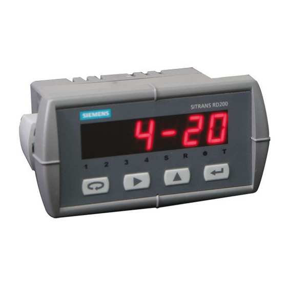
SITRANS RD200 SITRANS RD200 SITRANS RD200 is a universal input, panel mount remote digital display for process instrumentation. It accepts a single input of current, voltage, thermocouple, or RTD signals, and the four front panel buttons make the setup and programming an easy task. -
Page 6: The Manual
The Manual This manual provides instructions for the SITRANS RD200 remote display. The manual is designed to help you get the most out of your Remote Display, and it provides information on the following: • Product specifications • Outline diagrams •... -
Page 7: Specifications
• Operating temperature range: 0 to +65 °C (0 to +149 °F) • Storage temperature range: -40 to +85 °C (-40 to +185 °F) Relative humidity • Relative humidity: 0 to 90% non-condensing 7ML19985JS01 SITRANS RD200 – OPERATING INSTRUCTIONS Page 3... -
Page 8: Memory
• All relays rated 3A @ 30 V DC or 3A @ 250 V AC, non-inductive All relays are certified only for use with equipment that fails in a state at or under the rated maximums of the relays. Page 4 SITRANS RD200 – OPERATING INSTRUCTIONS 7ML19985JS01... -
Page 9: Serial Communications
Less than 2 ms (fixed) Appendix D - Serial Communication Protocol (PDC) Appendix E - Refer to on page 61 and Modbus Register Tables on page 85 for details. Software • SITRANS RD Software 7ML19985JS01 SITRANS RD200 – OPERATING INSTRUCTIONS Page 5... -
Page 10: Inputs
Approvals • CE • UL • Testing was conducted on SITRANS RD200 meters installed through the covers Note: of grounded metal enclosures with cable shields grounded at the point of entry representing installations designed to optimize EMC performance. Page 6 SITRANS RD200 –... -
Page 11: Dimensions
[0.5 Nm (4.5 lb/in) tightening torque] 62 mm (2.45") 81 mm 15 mm (3.2") (0.59") 91 mm (3.6") RD200 Case Dimensions - Top View 64 mm (2.5") 92 mm (3.61") 119 mm (4.68") 7ML19985JS01 SITRANS RD200 – OPERATING INSTRUCTIONS Page 7... - Page 12 Notes Page 8 SITRANS RD200 – OPERATING INSTRUCTIONS 7ML19985JS01...
-
Page 13: Installation
Unpacking Remove the meter from box. Inspect the packaging and contents for damage. Report damages, if any, to the carrier. If any part is missing or the meter malfunctions, please contact your local Siemens representative for assistance. Panel Mounting Instructions Prepare a standard 1/8 DIN panel cutout –... - Page 14 1.5 mm (0.060") max radius 45 mm panel cutout (1.772") to DIN 43700 tolerances: A: +0.8 mm (+0.032") -0.0 mm (-0.000 ") mounting mounting B: +0.6 mm (+0.024") bracket screw -0.0 mm (-0.000") Page 10 SITRANS RD200 – OPERATING INSTRUCTIONS 7ML19985JS01...
-
Page 15: Connections
Connector Labeling for Two Relays and 24 V Supply. The meter will operate regardless of DC polarity connection. The + and - symbols are only a suggested wiring convention. power connector AC or DC power required external fuse: 5 A max, slow blow 7ML19985JS01 SITRANS RD200 – OPERATING INSTRUCTIONS Page 11... -
Page 16: Signal Connections
The display may or may not show a fault condition depending on the nature of the overload. The fuse limits the current to a safe level when it detects a fault condition, and automatically resets itself when the fault condition is removed. Page 12 SITRANS RD200 – OPERATING INSTRUCTIONS 7ML19985JS01... - Page 17 SEtu The input type is selected using the Setup ( ) menu. Selected thermocouple input must correspond to thermocouple sensor and wire type used. Thermocouple input connections signal connector switch position 7ML19985JS01 SITRANS RD200 – OPERATING INSTRUCTIONS Page 13...
- Page 18 Lead wire compensation for two-wire RTDs can be applied using the Adjust ( ) menu. Offset adjustment (Adj) on page 42. Four-wire RTD input connections signal connector switch position sensor Page 14 SITRANS RD200 – OPERATING INSTRUCTIONS 7ML19985JS01...
-
Page 19: Serial Communication
For interfacing RS232 serial adapter RS232 RS422/485 serial adapter RS422/485 SITRANS RD200 meter copy cable Meter-to-meter (for cloning purposes - copying programmed settings from one meter to other meters) Relays and 24 V Output Connections Relay connections are made to a six-terminal connector labeled... - Page 20 24 V out 2-wire remote display, 4 to 20 mA chart recorder transmitter 4 to 20 mA Output Powered Externally mA out external power supply remote display, chart recorder Page 16 SITRANS RD200 – OPERATING INSTRUCTIONS 7ML19985JS01...
-
Page 21: Setup
59 for more details. Front panel buttons and status LED indicators Button Description Status Symbol Menu Alarm 1 Right arrow/Reset Alarm 2 Up arrow/Max Set point indicator Enter/Ack Reset point indicator 7ML19985JS01 SITRANS RD200 – OPERATING INSTRUCTIONS Page 17... -
Page 22: Display Functions And Messages
Set relay for automatic + manual reset any time Latching Set relay for latching operation LtCH Latching-cleared Set relay for latching operation with manual L-CL reset only after alarm condition has cleared Page 18 SITRANS RD200 – OPERATING INSTRUCTIONS 7ML19985JS01... - Page 23 Enter the Password menu PASS Unlocked Program password to lock meter unLC Locked Enter password to unlock meter LoCd Flashing display Overrange condition 9999 Underrange condition -1999 Open TC or RTD sensor open 7ML19985JS01 SITRANS RD200 – OPERATING INSTRUCTIONS Page 19...
-
Page 24: Main Menu
Input signal the meter will accept • Decimal point position for process inputs • Units (°F or °C) for temperature inputs • Relay operation • 4 to 20 mA analog output setup Page 20 SITRANS RD200 – OPERATING INSTRUCTIONS 7ML19985JS01... -
Page 25: Setting The Input Signal (Inpt)
Input menu. 4-20, 0-10, tC, rtd Press Up arrow to scroll through choices; 0-10 When is displayed, press Enter/Ack to accept this choice. Press Menu to return to Run Mode. 7ML19985JS01 SITRANS RD200 – OPERATING INSTRUCTIONS Page 21... - Page 26 Press Enter/Ack to set Fahrenheit or Celsius input. Press Up arrow to scroll through choices. Press Enter/Ack to accept a choice. 10. Press Menu to return to Run Mode. Page 22 SITRANS RD200 – OPERATING INSTRUCTIONS 7ML19985JS01...
-
Page 27: Setting The Decimal Point (Dec.p)
The temperature selection menu will only be available if the meter has been Note: Setting the input signal (inPt) setup for TC or RTD input. See on page 21. Press Enter/Ack to access the temperature selection menu. Press Up arrow to scroll through choices; 7ML19985JS01 SITRANS RD200 – OPERATING INSTRUCTIONS Page 23... -
Page 28: Setting Relay Operation (Rely)
(Automatic + manual reset at any time, non-latching), LtCH (Latching, manual reset only), L -CL (Latching with Clear, manual reset only after alarm condition has cleared), ALtr (Pump alternation control, automatic reset only), (Off, relay and status LED disabled). Page 24 SITRANS RD200 – OPERATING INSTRUCTIONS 7ML19985JS01... - Page 29 Press Enter/Ack to accept settings. is displayed. 10. Press Enter/Ack to set up fail-safe feature for relay 2 as in steps 7-9, or press Menu to exit and return to Run Mode. 7ML19985JS01 SITRANS RD200 – OPERATING INSTRUCTIONS Page 25...
- Page 30 The time delay will count down when the reset point is reached and the relay will turn off after the time delay has elapsed. Page 26 SITRANS RD200 – OPERATING INSTRUCTIONS 7ML19985JS01...
-
Page 31: Relay And Alarm Operation
Manual only after passing below Reset (latching with clear) For Manual reset mode, Enter/Ack can be pressed at any time to turn off relay. For relay to turn back on, signal must go below setpoint, and then go above it. 7ML19985JS01 SITRANS RD200 – OPERATING INSTRUCTIONS Page 27... - Page 32 Manual only after passing above Reset (latching with clear) For Manual reset mode, Enter/Ack can be pressed at any time to turn off relay. For relay to turn back on, signal must go above setpoint, and then go below it. Page 28 SITRANS RD200 – OPERATING INSTRUCTIONS 7ML19985JS01...
- Page 33 If the signal drops below the set point (high alarm) before the time delay has elapsed, the time delay timer resets and the relay does not change state. The same principle applies to the time delay. 7ML19985JS01 SITRANS RD200 – OPERATING INSTRUCTIONS Page 29...
- Page 34 Relay pressed Manual only after passing below Reset (latching with clear) The relay coil is energized in non-alarm condition. In case of a power failure, the relay will go to alarm state. Page 30 SITRANS RD200 – OPERATING INSTRUCTIONS 7ML19985JS01...
- Page 35 Relay pressed Manual only after passing above Reset (latching with clear) The relay coil is energized in non-alarm condition. In case of a power failure, the relay will go to alarm state. 7ML19985JS01 SITRANS RD200 – OPERATING INSTRUCTIONS Page 31...
- Page 36 Alternating pumps - mode: automatic (non-latching) Page 32 SITRANS RD200 – OPERATING INSTRUCTIONS 7ML19985JS01...
-
Page 37: Scaling The 4 To 20 Ma Analog Output (Aout)
Run Mode. For instructions on how to program numeric values see “Setting numeric Note: values” on page 20. The Analog Output menu is also used to program the Sensor break value in mA. 7ML19985JS01 SITRANS RD200 – OPERATING INSTRUCTIONS Page 33... -
Page 38: Program Sensor Break Output Value (Sebr)
The analog output reflects the display out of range conditions as follows: Input Condition Display Analog Output Underrange Flashing -1999 3.00 mA Overrange Flashing 9999 21.00 mA Open TC or RTD Flashing open Sensor break value Page 34 SITRANS RD200 – OPERATING INSTRUCTIONS 7ML19985JS01... -
Page 39: Programming The Meter (Prog)
10. Repeat steps 6 to 10 for the second input value. 11. Press Enter/Ack to confirm settings and return to Run Mode. For instructions on how to program numeric values. See “Setting numeric Note: values” on page 20. 7ML19985JS01 SITRANS RD200 – OPERATING INSTRUCTIONS Page 35... -
Page 40: Calibrating The Sitrans Rd200 (Cal)
0.20 VDC 100°F (56°C) 50°F (28°C) Calibrating the SITRANS RD200 (CAL) Recalibration is recommended at least every twelve months. The meter can be calibrated to display the process in engineering units by applying the appropriate input signal and following the calibration procedure. -
Page 41: Recalibrating Temperature Inputs (Cal)
J input). See “Thermocouple and RTD connections” on page 13. Set up the meter to accept the selected input (such as type J T/C). See “Setting the input signal (inPt)” on page 21. 7ML19985JS01 SITRANS RD200 – OPERATING INSTRUCTIONS Page 37... -
Page 42: Recalibrating Process Inputs (Ical)
The Internal Calibration (ICAL) menu, located in the Advanced features menu, is used to recalibrate the current and voltage inputs. Recalibration is recommended at least every twelve months. Internal calibration (ICAL) Refer to on page 48 for instructions. Page 38 SITRANS RD200 – OPERATING INSTRUCTIONS 7ML19985JS01... -
Page 43: Security
Program Mode. PASS Press Up arrow until is displayed. unLC Press Enter/Ack and enter previously set password. is displayed and meter returns to Run mode. Changes to programmed settings are now allowed. 7ML19985JS01 SITRANS RD200 – OPERATING INSTRUCTIONS Page 39... - Page 44 2. Ignore decimal point and sign. 3. Access the Password menu, add 2 to the noted reading and enter that number as the password (for example, display reading = -1.23, password = 0125). Page 40 SITRANS RD200 – OPERATING INSTRUCTIONS 7ML19985JS01...
-
Page 45: Advanced Features Menu
Set meter for either relay or analog output (factory set only – corresponding option installed) Intensity Select display intensity inty Analog output Set meter for analog output option Aout Relay Set meter for relay option rELy 7ML19985JS01 SITRANS RD200 – OPERATING INSTRUCTIONS Page 41... -
Page 46: Offset Adjustment (Adj)
RTDs. The offset adjustment value is automatically reset to zero whenever the type of temperature sensor is changed (i.e. Thermocouple type or RTD curve). Page 42 SITRANS RD200 – OPERATING INSTRUCTIONS 7ML19985JS01... -
Page 47: Noise Filter (Fltr)
The noise filter bypass value may be set anywhere from 0.2 to 99.9. It corresponds to percentage of full scale for process inputs and to degrees Fahrenheit for temperature inputs. Increasing the bypass value may slow down the display response to changes on the input signal. 7ML19985JS01 SITRANS RD200 – OPERATING INSTRUCTIONS Page 43... -
Page 48: Serial Communications (Serl)
Right arrow to advance to the next digit. Press Enter/Ack to accept display settings. Press Menu to exit at any time. Page 44 SITRANS RD200 – OPERATING INSTRUCTIONS 7ML19985JS01... -
Page 49: Select Menu (Selc)
SITRANS RD200 can also be connected directly to another RD200 meter through a cable assembly (SITRANS RD200 Meter Copy Cable). This allows the user to copy all the Meter copy function settings from one meter to another, using the Copy function. (See (CoPY) on page 47 See SITRANS RD Serial Adapters Instruction Manual for more details. - Page 50 Press Up arrow to scroll through the eight intensity levels. When the desired intensity level is displayed, press Ent/Ack to accept the setting. Press Menu to exit at any time. Page 46 SITRANS RD200 – OPERATING INSTRUCTIONS 7ML19985JS01...
-
Page 51: Sitrans Rd Software
SITRANS RD Software SITRANS RD software allows the SITRANS RD200 to be programmed from a PC and to act as a data logger. The software allows all setup parameters to be saved to a file for reporting, restoring, or programming other meters. -
Page 52: Internal Calibration (Ical)
CAUTION: Do not connect the two meters to the same 4 to 20 mA loop while cloning. Internal calibration may be affected. Connect the two meters using SITRANS RD200 meter copy cable or equivalent. Cable should not exceed 2.1 m (7 ft). - Page 53 1-3. Press Menu to exit at any time. The example above shows the calibration of the current input. The voltage input is calibrated in a similar way. 7ML19985JS01 SITRANS RD200 – OPERATING INSTRUCTIONS Page 49...
-
Page 54: Troubleshooting
If the meter is not working as expected, refer to the Diagnostics menu and Appendix B - Troubleshooting Tips on page 57 recommendations below. See also Page 50 SITRANS RD200 – OPERATING INSTRUCTIONS 7ML19985JS01... - Page 55 ), version ( ), and serial number ( ) information. Write down the information as it is displayed. Continue pressing Enter/Ack until all the information is displayed. Press Menu to exit at any time. 7ML19985JS01 SITRANS RD200 – OPERATING INSTRUCTIONS Page 51...
- Page 56 Notes Page 52 SITRANS RD200 – OPERATING INSTRUCTIONS 7ML19985JS01...
-
Page 57: Operation
Display will alternate between and maximum value for 10 seconds. Press Up arrow again to display the minimum reading since the last reset/ power-up. Display will alternate between and minimum value for 10 seconds. 7ML19985JS01 SITRANS RD200 – OPERATING INSTRUCTIONS Page 53... - Page 58 Press Right arrow to reset Max/Min while reading is being displayed. Max/ Min display readings are reset to actual reading. Press Menu to exit Max/Min display. Page 54 SITRANS RD200 – OPERATING INSTRUCTIONS 7ML19985JS01...
-
Page 59: Appendix A - Factory Defaults
20.00 mA diS2 Display 2 20.00 dd.dd Decimal point 2 places rLY1 Relay 1 Act1 Action 1 Automatic SEt1 Set 1 7.00 rSt1 Reset 1 6.00 rLY2 Relay 2 Act2 Action 2 Automatic 7ML19985JS01 SITRANS RD200 – OPERATING INSTRUCTIONS Page 55... - Page 60 The minimum timeout allowed is saved to memory if a lower value is entered (for example, if user enters 0.00 with a baud rate of 300, 0.06 is saved). Page 56 SITRANS RD200 – OPERATING INSTRUCTIONS 7ML19985JS01...
-
Page 61: Appendix B - Troubleshooting Tips
Serial adapter and cable or other programs Serial protocol selected Meter address and baud rate SITRANS Remote Display Software address and baud rate Other symptoms not described Contact your local Siemens above representative for assistance. 7ML19985JS01 SITRANS RD200 – OPERATING INSTRUCTIONS Page 57... - Page 62 Notes Page 58 SITRANS RD200 – OPERATING INSTRUCTIONS 7ML19985JS01...
-
Page 63: Appendix C - Quick User Interface Reference Guide
Auto & Manual Failsafe Reset point Latch Latch w/Clear Delays Pump Alt Failsafe 1 Analog Scale output Sensor Failsafe 2 break To Delays Set point Delay 1 To Program Delay 2 To Program 7ML19985JS01 SITRANS RD200 – OPERATING INSTRUCTIONS Page 59... - Page 64 Linéaire Copie Transmettre Modbus Racine carrée Sélectionner Fonction Protocole Débit inhibé Adresse Sortie Vitesse de transmission Intensité Retard de transmission TC ou RTD? Modbus? Etalonnage initial Time-out octet-octet Diagnostic Page 60 SITRANS RD200 – OPERATING INSTRUCTIONS 7ML19985JS01...
-
Page 65: Appendix D - Serial Communication Protocol (Pdc)
Serial Communication Protocol (PDC) SITRANS RD200 PDC This section describes how to communicate with the SITRANS RD200 meter using the Serial Communication Protocol (PDC). The user should be familiar with serial communications and the meter. Refer to the instruction manuals for the meter and the serial communication adapters for setup and wiring instructions. -
Page 66: Table Of Commands
4-20 mA Out – Data 4-20 mA Out – Mode 4-20 mA Out – Filter 4-20 mA Out – Limits 4-20 mA Out – Input and Output points Cutoff Value Linear/Exponential Selection Page 62 SITRANS RD200 – OPERATING INSTRUCTIONS 7ML19985JS01... -
Page 67: Command Packet Format
= 1 + 0x14 = 0x15 Therefore, the complete command packet that is sent = 0x01, “0026S015” , 0x03 In hex form = 0x01 0x30 0x30 0x32 0x36 0x53 0x30 0x31 0x35 0x03 7ML19985JS01 SITRANS RD200 – OPERATING INSTRUCTIONS Page 63... -
Page 68: Reply Packet Format
Incorrect amount of data in the data field Invalid data in the data field EEPROM write error Read Only Commands Code: 10 Description: Read Process Value Command Meter Meter ‘1’ ‘0’ ‘9’ ‘F’ (0x01) Address Address (0x03) Page 64 SITRANS RD200 – OPERATING INSTRUCTIONS 7ML19985JS01... - Page 69 The relay status represents the energized or de-energized state of the relay(s), and is active low logic (status 0 = relay energized). Relay Status Character Relay 2 Relay 1 character 7ML19985JS01 SITRANS RD200 – OPERATING INSTRUCTIONS Page 65...
- Page 70 Code: F0 Description: Read Product Identifier Command Meter Meter ‘F’ ‘0’ ‘8’ ‘ A ’ (0x01) Address Address (0x03) Page 66 SITRANS RD200 – OPERATING INSTRUCTIONS 7ML19985JS01...
-
Page 71: No-Data Commands
An example is shown for “01.234” . No-Data Commands Code: 30 Description: Reset the Maximum Process Value Command Meter Meter ‘3’ ‘0’ ‘9’ ‘D’ (0x01) Address Address (0x03) Reply ‘3’ ‘0’ ‘9’ ‘D’ (0x02) (0x03) 7ML19985JS01 SITRANS RD200 – OPERATING INSTRUCTIONS Page 67... - Page 72 Input configuration Bypass and Filter values Adjust value Relay parameters (whether installed or not) 4-20 mA output parameters (whether installed or not) Serial parameters and address There is no data in the reply. Page 68 SITRANS RD200 – OPERATING INSTRUCTIONS 7ML19985JS01...
-
Page 73: Read/Write Commands
Meter Meter ‘2’ ‘0’ ‘9’ ‘E’ (0x01) Address Address (0x03) Command: Write Meter Meter Check- Check- ‘2’ ‘0’ (0x01) Address Address (0x03) Reply: Write and Read Check- Check- ‘2’ ‘0’ (0x02) (0x03) 7ML19985JS01 SITRANS RD200 – OPERATING INSTRUCTIONS Page 69... - Page 74 Example: To program meter 00 for Type J thermocouple in degrees F: Command packet: = 0x01, “00202380D1” , 0x03 In hex form = 0x01 0x30 0x30 0x32 0x30 0x32 0x33 0x38 0x30 0x44 0x31 0x03 Page 70 SITRANS RD200 – OPERATING INSTRUCTIONS 7ML19985JS01...
- Page 75 Reply: Write and Read Check- Check- ‘2’ ‘2’ ‘+’ ‘0’ ‘0’ ‘0’ (0x02) (0x03) The data field is 7 characters consisting of “+000” followed by the value. Valid values are 000, and 002 to 199. 7ML19985JS01 SITRANS RD200 – OPERATING INSTRUCTIONS Page 71...
- Page 76 Command: Write Meter Meter ‘+’ Check- Check- ‘2’ ‘4’ ‘0’ ‘0’ ‘0’ X (0x01) Address Address ‘-‘ (0x03) Reply: Write and Read ‘+’ Check- Check- ‘2’ ‘4’ ‘0’ ‘0’ ‘0’ (0x02) ‘-‘ (0x03) Page 72 SITRANS RD200 – OPERATING INSTRUCTIONS 7ML19985JS01...
- Page 77 Code: 27 Description: Relay Operating Parameters Command: Read Meter Meter Relay Check- Check- ‘2’ ‘7’ (0x01) Address Address (0x03) 7ML19985JS01 SITRANS RD200 – OPERATING INSTRUCTIONS Page 73...
- Page 78 Relay Check- Check- ‘2’ ‘8’ (0x01) Address Address ‘1’ (0x03) Command: Write Meter Meter ‘0’ Relay Check- Check- ‘2’ ‘8’ ‘+’ ‘0’ ‘0’ ‘0’ X X X (0x01) Address Address ‘1’ (0x03) Page 74 SITRANS RD200 – OPERATING INSTRUCTIONS 7ML19985JS01...
- Page 79 Turn-On Time Delay. The delay number is “+000” followed by the value in seconds. The range is 000 to 199. Relay numbers start with zero, but in the meter instruction manuals, relay Note: numbering starts with one. 7ML19985JS01 SITRANS RD200 – OPERATING INSTRUCTIONS Page 75...
- Page 80 Note that if a relay is not in a mode that allows acknowledgement, it will not be acknowledged. Relay numbers start with zero, but in the meter instruction manuals, relay Note: numbering starts with one. Page 76 SITRANS RD200 – OPERATING INSTRUCTIONS 7ML19985JS01...
- Page 81 ’6’ dddddd (no decimal) CAUTION: Starting with SITRANS RD200 Version 3.000, if the presently selected input is either mA or V, writing a new decimal point using this command will immediately update the displayed decimal point also. 7ML19985JS01 SITRANS RD200 – OPERATING INSTRUCTIONS...
- Page 82 4-20 mA output. The reply will be –99.99 to indicate this improper operation. Refer to Command 41 (next) for Modes. Code: 41 Description: 4-20 mA Output - Mode Command: Read Meter Meter ‘4’ ‘1’ ‘9’ ‘B’ (0x01) Address Address (0x03) Page 78 SITRANS RD200 – OPERATING INSTRUCTIONS 7ML19985JS01...
- Page 83 Command: Write Meter Meter Check- Check- ‘4’ ‘2’ ‘+’ ‘0’ ‘0’ ‘0’ ‘0’ X (0x01) Address Address (0x03) Reply: Write and Read Check- Check- ‘4’ ‘2’ ‘+’ ‘0’ ‘0’ ‘0’ ‘0’ (0x02) (0x03) 7ML19985JS01 SITRANS RD200 – OPERATING INSTRUCTIONS Page 79...
- Page 84 ’0’ Sensor Break Value ’1’ Overrange Value ’2’ Underrange Value ’3’ Max Value Allowed ’4’ Min Value Allowed Only the Sensor Break Value can be accessed through the front panel menu. Note: Page 80 SITRANS RD200 – OPERATING INSTRUCTIONS 7ML19985JS01...
- Page 85 -1999 to +9999 ’2’ DAC Output 1 00.00 to +23.99 ’3’ DAC Output 2 00.00 to +23.99 Code: 47 Description: Cutoff Value Command: Read Meter Meter ‘4’ ‘7’ ‘9’ ‘5’ (0x01) Address Address (0x03) 7ML19985JS01 SITRANS RD200 – OPERATING INSTRUCTIONS Page 81...
- Page 86 Note that the write command does not include the decimal point regardless of the decimal point setting. Page 82 SITRANS RD200 – OPERATING INSTRUCTIONS 7ML19985JS01...
- Page 87 Linear: DisplayValue = (ADC_count * Gain) + Offset, Exponent: DisplayValue = ((ADC_count – Input_low) * Gain) + Offset, where Input_low, Gain, and Offset are user defined, either through scaling or external calibration. 7ML19985JS01 SITRANS RD200 – OPERATING INSTRUCTIONS Page 83...
- Page 88 Notes Page 84 SITRANS RD200 – OPERATING INSTRUCTIONS 7ML19985JS01...
-
Page 89: Appendix E - Modbus Register Tables
Appendix E - Modbus Register Tables This section describes how to communicate with the SITRANS RD200 meter using the ® Modbus RTU Serial Communication Protocol. The user should be familiar with Modbus serial communication and the meter. Refer to the instruction manuals for the meter and the serial communication adapters for setup and wiring instructions. - Page 97 Write the desired values for the input, Input 1 & 2, for mA or volts. Note that the values written to SITRANS RD200 are (mA * 100) or (volts * 100) because of the meter’s input specifications (4 digit, 20.00 mA and 10.00 volt input ranges).
- Page 98 BCD (i.e. only nybbles between 0 and 9. If a nybble between A and F is sent, no change to lock status will occur and the return value will be 0xFF00). ® Modbus is a Registered Trademark of Schneider Automation Inc. Page 94 SITRANS RD200 – OPERATING INSTRUCTIONS 7ML19985JS01...
-
Page 100: Decimal Point For Rd200
7 – 5 2 – 0 Normal/ Function 00000000 Operation Fail-Safe Automatic Normal reset Auto & Man- Fail-Safe ual reset Latching Latching with Clear Pump Alter- nation Unused Unused Off (Disabled) (Modbus accessible) Page 96 SITRANS RD200 – OPERATING INSTRUCTIONS 7ML19985JS01... - Page 102 Notes Page 98 SITRANS RD200 – OPERATING INSTRUCTIONS 7ML19985JS01...
- Page 103 ........85 list ............55 Mounting loading instructions ......55 ambient temperature ......3 installation category ......4 location .............3 Inputs range ............4 mA ..............6 relative humidity ........3 specifications ..........6 temperature input ........6 7ML19985JS01 SITRANS RD200 – OPERATING INSTRUCTIONS Page 99...
- Page 104 ..........15 tips ............57 Modbus protocol ......... 85 PDC protocol ......... 61 setup ............5 Voltage software ............5 connections ...........12 Setup decimal point ........23 Weight fail-safe operation ....... 25 specifications ..........6 Page 100 SITRANS RD200 – OPERATING INSTRUCTIONS 7ML19985JS01...
- Page 106 For more information www.siemens.com/level www.siemens.com/weighing Siemens AG Subject to change without prior notice Industry Sector 7ML19985JS01 Rev. 1.3 1954 Technology Drive P.O. Box 4225 *7ml19985JS01* © Siemens AG 2012 Peterborough, ON Canada K9J 7B1 Printed in Canada email: techpubs.smpi@siemens.com www.siemens.com/processautomation...
Need help?
Do you have a question about the SITRANS RD200 and is the answer not in the manual?
Questions and answers