
Related Manuals for Siemens FT2011


Summary of Contents for Siemens FT2011
- Page 1 FT2011 Floor repeater display Operation Manual Building Technologies 009311_k_en_-- 2015-12-15 Control Products and Systems...
- Page 2 Issued by: Siemens Switzerland Ltd. Building Technologies Division International Headquarters Gubelstrasse 22 CH-6301 Zug Tel. +41 41 724-2424 www.siemens.com/buildingtechnologies Edition: 2015-12-15 Document ID: 009311_k_en_-- © Siemens Switzerland Ltd, 2006 2 | 32 Building Technologies 009311_k_en_-- Fire Safety 2015-12-15...
-
Page 3: Table Of Contents
Table of contents About this document ................5 Displays used in document ................. 7 Applicable documents ................. 7 Download center ..................8 Technical terms and abbreviations .............. 8 Revision history ..................8 Safety ....................9 Safety instructions ..................9 Safety regulations for the method of operation ...........11 Standards and directives complied with............13 2.3.1 CPR conformity and firmware version .........13... - Page 4 4 | 32 Building Technologies 009311_k_en_-- Fire Safety 2015-12-15...
-
Page 5: About This Document
1 About this document Goal and purpose This document describes the operation of the floor repeater display FT2011 in a fire detection system. The reader shall become familiar with the possible indications and operating functions on the floor repeater display, as well as with the functionality of the floor repeater display in the overall system. - Page 6 About this document Displays used in document Conventions for text marking Markups Special markups are shown in this document as follows: ⊳ Requirement for a behavior instruction Behavior instruction with at least two operation sequences – Version, option, or detailed information for a behavior instruction ⇨...
-
Page 7: Displays Used In Document
About this document Displays used in document 1.1 Displays used in document The form of display in the document sometimes uses tables. Deviations between the original and the table representation are shown below as examples: ABCDE FGHI 07:55:31 ABCD: 3 !ABCD: 421 ABC: 32 XXX YYY ZZZ... -
Page 8: Download Center
You can download various types of documents, such as data sheets, installation instructions, and license texts via the following Internet address: http://siemens.com/bt/download Enter the document ID in the 'Find by keyword' input box. You will also find information about search variants and links to mobile applications (apps) for various systems on the home page. -
Page 9: Safety
Safety Safety instructions 2 Safety 2.1 Safety instructions The safety notices must be observed in order to protect people and property. The safety notices in this document contain the following elements: ● Symbol for danger ● Signal word ● Nature and origin of the danger ●... - Page 10 Safety Safety instructions How risk of injury is presented Information about the risk of injury is shown as follows: WARNING Nature and origin of the danger Consequences if the danger occurs ● Measures / prohibitions for danger avoidance How possible damage to property is presented Information about possible damage to property is shown as follows: NOTICE Nature and origin of the danger...
-
Page 11: Safety Regulations For The Method Of Operation
2.2 Safety regulations for the method of operation National standards, regulations and legislation Siemens products are developed and produced in compliance with the relevant European and international safety standards. Should additional national or local safety standards or legislation concerning the planning, mounting, installation,... - Page 12 Disregard of the safety regulations Before they are delivered, Siemens products are tested to ensure they function correctly when used properly. Siemens disclaims all liability for damage or injuries caused by the incorrect application of the instructions or the disregard of danger warnings contained in the documentation.
-
Page 13: Standards And Directives Complied With
Safety Standards and directives complied with 2.3 Standards and directives complied with A list of the standards and directives complied with is available from your Siemens contact. 2.3.1 CPR conformity and firmware version In order to satisfy Ordinance No. 305/2011 (the Construction Products Regulation –... -
Page 14: Features
Features Maximum number of events that can be displayed 3 Features The ↑ floor repeater display is an indication and operating unit in a fire detection installation with the following functions: Indication of events ● 'ALARM' – 'Pre-ALARM' ● 'Fault' ●... -
Page 15: Pmi
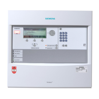
Buttons on the PMI 4 PMI The figure below shows the PMI of a ↑ floor repeater display. Figure 2: PMI, floor repeater display 'ALARM' LEDs 'More alarms' button Display LED, configurable Navigation buttons LED 'System On' 'Silence buzzer' button 4.1 Buttons on the PMI Navigation buttons The navigation buttons work in the same way as the arrow keys on a PC keyboard. -
Page 16: Display
Display 4.2 Display The display has two areas: ABCDE FGHI 07:55:31 ABCD: 3 ABCD: 421 ABC: 32 XXX YYY ZZZ ABCDEFGHI AAA/BBB ABCD: 026 ABC: 75 XXX YYY ZZZ ABCDE CCC Figure 3: Display representation with two indicated messages Header Representation area 4.3 LEDs The LEDs on the ↑Person Machine Interface signal 'Events' and conditions. -
Page 17: Service Menu
Service menu 5 Service menu Various settings can be performed using a service menu. You can open the service menu using a keyboard shortcut (see corresponding chapter). After calling up the menu and entering a password, the following menu items are available: ●... -
Page 18: Operation
Operation ALARM Procedure 6 Operation 6.1 ALARM Procedure If your fire detection system has no delayed alarm transmission function ('AVC'), the variant –'Fire Brigade in' 'mm:ss' in Step 1 (see Procedure in the event of alarm) does not apply. Figure 4: ALARM operation sequence Read the top line Read off the fire location 18 | 32... -
Page 19: Procedure In Case Of Fault
Operation Procedure in case of Fault Procedure in the event of alarm Action / Condition Consequence / Status Step Read top line on display – 'Fire Brigade requested' 'ALARM' is transmitted to the fire brigade – 'Fire Brigade in' 'mm:ss' 'ALARM' is transmitted to fire brigade in 'mm:ss' Remaining time is shown as Countdown –... -
Page 20: Indicating And Scrolling In Lists
Operation Indicating and scrolling in lists 'Fault' and 'Intervention Concept' ('IC') On consideration of 'Intervention Concept', events of the 'Fault' category can be assigned their own sequence. This sequence may be configured differently and depends on the 'Manned operation' / 'Unmanned operation' operation mode. An exemplary sequence after a 'Fault', on consideration of the 'Intervention Concept', is graphically represented in the following: 'Fault' has occurred... -
Page 21: Open Service Menu / Select Menu Item
Operation Open service menu / Select menu item 6.4 Open service menu / Select menu item To open the service menu a keyboard shortcut as well as a password are required. The service menu can only be opened when no 'Event' is displayed. Opening the service menu w No 'Event' are displayed. -
Page 22: Alarm Verification Concept (Avc)
Alarm verification concept (AVC) Open service menu / Select menu item 7 Alarm verification concept (AVC) The ↑ 'Alarm Verification Concept' serves the purpose of delayed alarm transmission and takes into account the interaction of the operating personnel in the alarming sequence. Operating personnel are able to examine the indicated fire location in the event of a fire alarm. -
Page 23: Attendance Check
Alarm verification concept (AVC) Attendance check 7.1 Attendance check Should an event ('Pre-ALARM', 'ALARM') arise, the operating personnel may acknowledge presence within the time t1. After acknowledgement, the investigation time t2 starts. If presence is not acknowledged within the given time t1, ↑ global alarming is activated. - Page 24 Alarm verification concept (AVC) Example of a verification process t1.. t2..t1 X ..t2 X Figure 5: Alarm verification Alarm event Acknowledge at ↑ 'Station' Local alarming Not acknowledged Manual call point or <Alarm delay off> on t2.. Time t2 to investigate the source of alarm / the 'Station' fire location 'Unmanned operation' operation mode...
-
Page 25: Fire Alarming
Alarm verification concept (AVC) Fire alarming 7.4 Fire alarming Alarming is controlled at 'Area' level. During alarming the ↑ alarming equipment is activated, e.g., ↑ alarm devices and remote transmission devices. ↑ Alarm devices For ↑ local and ↑ global alarming, acoustic alarm devices, beacons, digital outputs, etc., can be used. - Page 26 Alarm verification concept (AVC) Fire alarming The ↑ alarm devices and the remote transmission can be separately configured for: ● Alarm type (only with automatic zones) – 'Pre-ALARM' – 'ALARM' ● Zone type (only with 'ALARMS') – Manual alarm – Automatic alarm –...
-
Page 27: Faults / Troubleshooting
Faults / Troubleshooting 8 Faults / Troubleshooting If the ↑ 'Site' displays a 'Fault', the table below provides a list of all possible 'Faults', including information on the possible causes. If a 'Fault' cannot be eliminated with the help of these operation instructions, please contact the service engineer. -
Page 28: Maintenance
Maintenance 9 Maintenance Please adhere to the local provisions. No maintenance work is required. Cleaning the PMI To clean the PMI use a wet cloth without any cleaning agents, abrasives or solvents. 28 | 32 Building Technologies 009311_k_en_-- Fire Safety 2015-12-15... -
Page 29: Glossary
Glossary Glossary Minor incident Alarm device Alarm situation which the operating personnel Element in the fire detection system for acoustic can handle themselves and does not, therefore, and/or visual alarming, e.g. alarm sounder, trigger global alarming. beacon. Alarm verification concept The arrangement of operating and display Concept for preventing false alarms which takes elements on a fire control panel or on a fire... -
Page 30: Index
Index Index Alarm verification concept AVC ..............22 Example of verification process ....... 23 Alarm verification concept ....... 22 Example of verification process ....... 23 Download center URL ..............8 LEDs Colors ............. 16 Original language Source language..........5 Source language ..........5 30 | 32 Building Technologies 009311_k_en_--... - Page 31 Index 31 | 32 009311_k_en_-- Building Technologies Fire Safety 2015-12-15...
- Page 32 Issued by © Siemens Switzerland Ltd, 2006 Siemens Switzerland Ltd Technical specifications and availability subject to change without notice. Building Technologies Division International Headquarters Gubelstrasse 22 CH-6301 Zug +41 41-724 24 24 www.siemens.com/buildingtechnologies Document ID: 009311_k_en_-- Manual FS20/FS720 Edition: 2015-12-15...
Need help?
Do you have a question about the FT2011 and is the answer not in the manual?
Questions and answers