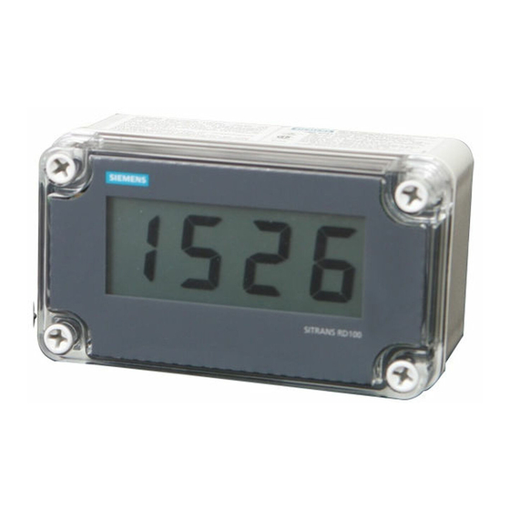
Table of Contents
Advertisement
Quick Links
RD100 Remote Display - Approval
Connections Control Drawing
RD100 FM APPROVED & CSA CERTIFIED LOOP-POWERED METER
SECTION AGENCY DESCRIPTION
1.0
General Notes
2.0
FM/CSA
Conduit Installation Instructions
3.0
FM
Single or Dual Channel Positive Polarity
Intrinsic Safety Barrier
4.0
CSA
Single or Dual Channel Instrinsic Safety
Barrier Entity Installation
NOTE: FM AND CSA CONTROLLED DOCUMENT.
NO CHANGES WITHOUT PRIOR FM AND CSA APPROVAL.
1.0 GENERAL NOTES
1.1 For Class II, Class III (Division 1 and 2) and NEMA/CSA
type 4X installations, use conduit hub which is listed/certified
for the environment in which the indicator is installed.
1.2 For Class II and III (Division 1 and 2) installations, field wiring
must enter the enclosure through a listed/certified dust-tight
conduit seal.
1.3 Control room equipment must not use or generate more than
250 VRMS or VDC.
1.4 US installations must be in accordance with ANSI/ISA
RP12.06.01 "Installation of Intrinsically Safe Systems for
Hazardous (Classified) Locations" and the National Electrical
Code (ANSI/NFPA 70). Canadian installations must be in
accordance with the Canadian Electrical Code, Part 1.
1.5 Hazardous location installation instructions for associated
apparatus (barrier) must also be followed when installing this
equipment.
1.6 For safe installation of a FM Approved/CSA Certified
transmitter in series with RD100 loop indicator, the hazardous
location installation instructions for the transmitter, RD100 loop
indicator, and associated apparatus (barrier) must be compatible.
1.7 RD100 indicator does not add capacitance or inductance to loop
under normal or fault conditions.
1.8 Substitution of components may impair hazardous location
safety.
2.0 RD100 CONDUIT INSTALLATION INSTRUCTIONS
2.1 Remove the Display from the enclosure and connect ½" conduit
fittings to the hole provided. For enclosures without a
pre-drilled hole, the installer must make a hole in accordance
with the instructions for the particular conduit fitting being
installed.
2.2 Use only UL/CSA conduit hubs that are specified to maintain
NEMA 4X and Class II / Class III ratings.
2.3 Conduit hubs must be connected to the conduit prior to being
connected to the enclosure.
2.4 Enclosure must be mounted using the mounting holes located in
the base external to the equipment cavity.
7ML19985JY01
Intrinsic Safety Barrier Connections
SITRANS RD100 – CONTROL DRAWING
3.0 RD100 FM INSTALLATION WIRING DIAGRAM
Using single or dual channel intrinsic safety barrier
Application Notes:
3.1 U i > U o of single channel barrier or V t of dual channel
barrier
3.2 I i > I o of single channel barrier or I t of dual channel barrier
3.3 L i plus interconnecting wiring < L o of single or dual channel
barrier
3.4 C i plus interconnecting wiring < C o of single or dual channel
barrier
3.5 It is not necessary to use intrinsic safety barriers when installing
the RD100 in Class I,II,III, Division 2, Groups ABCDFG,
maximum input voltage = 30 VDC.
4.0 RD100-CSA INSTALLATION WIRING DIAGRAM
Using single or dual channel intrinsic safety
barrier-entity installation
Application Notes:
4.1 Barrier parameters must meet the following requirements:
V oc or U o ≤ V max or U i
I sc or I o ≤ I max or I i
C a or C o ≥ C
+ C cable
i
L a or L o ≥ L i + L cable
P o < P i
4.2 For CSA Certification, barrier and transmitter must be CSA
Certified with Entity Parameters and must be connected per
manufacturer's instructions.
July 2007
Advertisement
Table of Contents

Summary of Contents for Siemens SITRANS RD100
- Page 1 L a or L o ≥ L i + L cable P o < P i 4.2 For CSA Certification, barrier and transmitter must be CSA Certified with Entity Parameters and must be connected per manufacturer’s instructions. 7ML19985JY01 SITRANS RD100 – CONTROL DRAWING July 2007...
- Page 2 Maximum Voltage Drop Note: The information contained here concerns only the SITRANS RD100 CE version. For additional information, please consult the complete RD100 instruction manual on the enclosed CD. • 1 V at 20 mA • 4 V at 20 mA with optional backlight active Note: Except where noted, all specifications apply to operation at +25 °C (+77 °F).


Need help?
Do you have a question about the SITRANS RD100 and is the answer not in the manual?
Questions and answers