Do you have a question about the CTT-1C-D24 and is the answer not in the manual?
Questions and answers
Ron Hurst
April 28, 2025
How to set oven or time on CTT-1-C-D24
1 comments:
Mr. Anderson
May 15, 2025
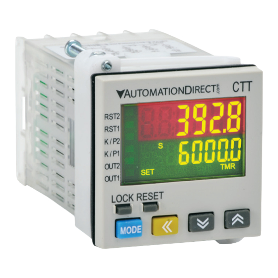
To set the timer on the Automation Direct CTT-1C-D24:
1. Enter Timer Settings: Press the key in the main menu for more than 3 seconds to enter the parameter setting page.
2. Select Mode: Choose the timer mode by selecting one of the following: - `–funC` > `time` (Timer) - Other available modes: counter, tachometer, or mixed mode.


Need help?
Do you have a question about the CTT-1C-D24 and is the answer not in the manual?
Questions and answers
How to set oven or time on CTT-1-C-D24
To set the timer on the Automation Direct CTT-1C-D24:
1. Enter Timer Settings: Press the key in the main menu for more than 3 seconds to enter the parameter setting page.
2. Select Mode: Choose the timer mode by selecting one of the following:
- `–funC` > `time` (Timer)
- Other available modes: counter, tachometer, or mixed mode.
3. Select Timer Direction:
- `t–mode` > `–up` (Timing up) or `–down` (Timing down)
4. Select Output Mode:
- `t–otmd` > Choose from 12 output modes like `sond1`, `sond2`, `soffd`, `rCy`, etc., depending on your need (e.g., repeat cycles, on-delay, etc.)
5. Select Time Unit:
- `t–unit` > Choose units like `ms–001` (1 ms), `s–001` (1 sec), `m–01` (1 min), `h–1` (1 hour), etc.
6. Set Time Values: Use the up/down keys to set the desired time for the ON and OFF periods.
7. Save and Exit: After setting all parameters, press the key for more than 3 seconds to return to the main menu.
This will configure the timer function according to your requirements.
This answer is automatically generated