Advertisement
Quick Links
TAKARA BELMONT CORPORATION
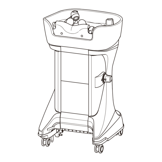
YUME OASIS Installation Instructions
Upper unit
Side Wash Basin
Model No.AY-OAYMSS-*
The "*" part of the individual Model No.
shown above depends on the product color.
The CAUTIONs listed here are to ensure that YUME OASIS can be installed safely, and to prevent and danger or
risk to the person installing YUME OASIS or those around them.
All of these CAUTIONs are important for safety. TAKARA BELMONT is not responsible for any damage or risk
to the person installing YUME OASIS or those around them due to accidents if YUME OASIS is installed
without adhering to the CAUTIONs.
CAUTION
If YUME OASIS is installed after ignoring this symbol, there is the risk of light or moderate injury or physical damage.
Upper unit
Back Wash Basin
(YUME Basin)
Model No.AY-OAYMYM-*
AY-OAYMYM-*NB
The latter of Model No. is without "NB"
This product is battery specification.
Be prepared for AA size battery
(LR6,2 pcs)[not included]
Floor unit
Model No.AY-OAYM-F
Before Installation
Usage Conditions
Preparation Before Installation Of floor unit
YUME OASIS Packing
Installation Of Floor Unit
Piping In Floor Unit
Carrying The Upper Unit
Connection Check With The Upper Unit
Test Water Flow
Cleaning And Check Of The Floor Unit
Cleaning And Check Of The Upper Unit
After Installation
Specifications
Chair Correlation Dimension
M E M O
To the installer
・The instructions should be thoroughly read and
understood before installation to ensure that YUME OASIS
is installed correctly.
・After installation, give these instructions to the customer.
To the customers
・Customers must not install YUME OASIS by themselves.
・Please give us your order of installation.
Never install this product by yourself.
・Customers must store these instructions in a safe place
so as not to lose them.
※ The actual shape of YUME OASIS and the images and
dimensions listed in these instructions may be modified
and are subject to change without notice.
3rd Edition
1
Contents
March 2017
2
5
6
1 2
1 3
1 6
1 8
22
23
24
25
27
29
30
3 5
Advertisement

Subscribe to Our Youtube Channel
Related Manuals for Takara Belmont Yume Oasis


Summary of Contents for Takara Belmont Yume Oasis
- Page 1 YUME OASIS or those around them due to accidents if YUME OASIS is installed without adhering to the CAUTIONs. CAUTION If YUME OASIS is installed after ignoring this symbol, there is the risk of light or moderate injury or physical damage. 3rd Edition March 2017...
- Page 2 Before Installation ● Plumbing Drawing ・Horizontal Plumbing (Unit: mm) *1 Drain 60 to 70 (Distance to the socket end) Hot water supply 45 to 55 (Distance to the socket end) Water supply イス側 Seat side *2 50以上 *3 Center line Piping space Hot water supply Rc1/2 13 mm Water supply Rc1/2 13 mm...
- Page 3 ● Plumbing Layout Of Horizontal Plumbing Stop valve Flexible hose (accessory) (accessory) Flexible hose (accessory) Drain VU40 Water supply Rc1/2 13 mm Flexible hose (accessory) Hot water supply Rc1/2 (Copper pipe: 13 mm) Hot water supply Pipe (Copper pipe of 20 CP or more) Water supply Pipe (PVC pipe of 20 VP or more, Seat side...
- Page 4 ・This product is designed for indoor installation. Always install this product indoors. ■ Plumbing ● Diameter of pipes and gradient of drain line ・Use dependent drainage for YUME OASIS only. ・Layout the drain line in a straight line as best as possible. Number of upper units to...
- Page 5 ・Use a pressure set between 0.1 to 0.4 MPa (1 to 4 kg f/cm2). Hot water supply, If multiple YUME OASIS are used, ensure that the pressure does not drop below 0.1 MPa (1 kg f/cm2). water supply ・Set the water supply pressure ≧ hot water supply pressure.
- Page 6 Preparation Before Installation Of Floor Unit There are two preparation methods for installation; "Mortar Bury Method" and "Composite Panel Platform Method". Select either of the methods according to the installation site conditions. Refer to the following procedure for Mortar Bury Method, and refer to page 9 for Composite Panel Platform Method. In the case of the mortar bury method, a wooden form and a bury frame (our optional item) are required.
- Page 7 [Form] Cut off three portions according to pipe positions. ※ When installing the floor unit, fine adjustment will be required. Be sure to install in the following order: (1) Install a form and install mortar base. (2) Install a bury frame and install mortar filling. Mortar Base 4 Installation of mortar base Install mortar base.
- Page 8 ※ Even in the case of the installation site with wood flooring or tiles used around the openings, laminate 3 mm thick hard floor panels made of PVC tiles. ※ For the floor panels to laminate, the optional YUME OASIS floor panel kit is available in two colors. Place another order if necessary.
- Page 9 ■ Composite Panel Platform Method 1 Marking (floor level) Mark the floor level (F.L.) CAUTION Always ensure the gradient of drain line according to the number of units to be installed as shown on page 4. 140 mm or more 2 Illustrates the markings (installation position), the support legs and the base panel and mark the position to place the floor unit.
- Page 10 5 Lamination of floor panels After laying the subflooring material and the finishing material on the base, attach the reinforcement frame for unit mounting onto the back surface of the subflooring material. Finishing material (t 12) Subflooring material (t 12) ※ Check the flexural level of the floor base panel again and place additional support legs under the reinforcement frame if required. ※Dimensions of the reinforcement frame for unit mounting CAUTION 591㎜...
- Page 11 ※ Even in the case of the installation site with wood flooring or tiles used around the openings, laminate 3 mm thick hard floor panels made of PVC tiles. ※ For the floor panels to laminate, the optional YUME OASIS floor panel kit is available in two colors. Place another order if necessary.
- Page 12 YUME OASIS Packing ■ YUME OASIS Packing Tick the boxes below to confirm that all contents are provided. ● Floor unit □ Floor unit main body …1 □ Flexible pipe □ Stop valve…1 (long/middle/short and for hot water/ (for hot water/water pipes)…2 water supplies)…1 (for each) (Long)...
- Page 13 1 Installation Of Floor Unit ※ A wrong installation procedure of this product may prevent proper installation of the basin body or the chair body. Make sure to follow the installation procedure below: 1 Take out the floor unit from the packing. Hold the sections indicated by the arrows to take out the unit.
- Page 14 3 Fitting the floor unit into the floor Long nut Hold the rotational shaft of the top panel swing and the Cap nut sash, and then fit the floor unit into the following parts; * Hold here. ・Mortar bury method; bury frame ...
- Page 15 5 Adjust the adjuster 1. Loosen the level adjuster nut. Central adjuster Corner adjuster [Resin case top view] Cap nut Cap nut Level adjuster nut Resin case of Resin case of floor unit floor unit Adjuster Central adjuster Corner adjuster POINT 1 2.
- Page 16 2 Piping In Floor Unit 1 Attachment of stop valve 1. Confirm that the ascending part of the pipe is in accordance Stop valve with the plumbing drawing. 2. Attach the stop valve to the pipes for hot water supply and water supply.
- Page 17 ● When attaching the water supply Pipe and hot water supply Pipe, ensure that they do not come in contact with the basin pipes. Doing so will may cause water leaks. ● Always attach the supplied packing. Using YUME OASIS without installing the supplied packing may cause water leaks.
- Page 18 4 Attachment of lid Straight slot screwdriver Attach the lid to the floor unit and then tighten the screw for fastening lid with a straight slot screwdriver. Screw for fastening lid ※ The screw for fastening lid can be tightened with a coin, etc. 4...
- Page 19 ■ Attachment Of Batteries <Back Wash Basin (YUME Basin) The latter of Model No. is without " NB" > This product is battery specification. Be prepared for AA size battery (LR6,2 pcs)[not included] This product has a function to sound a warning beep in the case of dangerous action to the basin such as pushing up the basin by the chair back rest.
- Page 20 2. Remove the maintenance cover. Hold the bottom of the maintenance cover and pull it to remove. Maintenance cover Base cover Hold the bottom of the maintenance cover and pull it to remove. CAUTION The base cover may be damaged. 2.
- Page 21 3. Make the bottom of the maintenance cover caught by the loosened screws. Maintenance cover Screw Maintenance cover Base cover Packing Screw Maintenance cover CAUTION Forcible attachment may damage the cover. Packing Screw When the maintenance cover is attached, pay attention not to hit the base cover. Forcible attachment may damage the cover.
- Page 22 5 Connection Check With The Upper Unit Open the top panel swing. 2. While the assist button is held down, use another 1. Step on the assist button to lift the release lever. foot to raise the release lever to the angle shown in the image.
- Page 23 6 Test Water Flow 1 Test the water flow. CAUTION ● Always test the water flow to prevent accidents during use. ● When the product is shipped, the faucet handle (on the basin) is not tightly closed up. If you open the stop valve while the upper unit is connected, water may come out from the shower head. ※...
- Page 24 7 Cleaning And Check Of The Floor Unit ■ Cleaning Be sure to clean the strainer (incorporated in the check valve) of the floor unit after the flow test is finished. If not cleaned, enough amount of water may not come out from the shower or troubles may occur in temperature adjustment.
- Page 25 ■ Checking Of Floor Unit For checking of the floor unit, refer to the followings; Be sure to check the floor unit in order to prevent accidents in operation. CAUTION 1. No leakage in the piping connection part. The connection may get loosen during transportation. Tighten the piping connection part in the floor unit again.
- Page 26 ■ Countermeasure Against Low Water Pressure ※ When the both pressures of hot water/water supplies are 0.18 MPa (1.8 kg f/cm2) or less, select the floor unit "without pressure reducing valve". ※ If the hot water or water supply pressure is too low and the outlet flow from the shower head is small (7.6 L/min or less for a rough guide), change the pressure reducing valve to the joint (our optional item EA-OARS-T).
- Page 27 After Installation ■ Attachment Of The Hair Trap And The Drain Cap Put the hair trap into the drain port and place the drain cap on the top as shown in the image. Drain cap Drain cap Hair trap Hair trap ■...
- Page 28 <Side Wash Basin > 1. Align the neck cushion to the center of 2. Align the height of the neck core and neck cushion ends (both ends). neck core as the below. Fix the hook light pulling the neck cushion on the Check the direction of the neck cushion-and neck core.
- Page 29 Specifications (YUME OASIS) AY-OAYMYM-* Model No. AY-OAYMSS-* AY-OAYMYM-*NB Thermo mixing system Faucet fittings Thermo mixing system Outlet Switching system (aerator/shower) Switching system (aerator/shower) Outlet flow rate Aerator: Approximately 7.5 L/min Aerator: Approximately 8.0 L/min (hot water supply pressure, Aerator: Approximately 9.5 L/min Aerator: Approximately 8.5 L/min...
- Page 30 Chair Correlation Dimension ■ Back Wash Basin (YUME Basin) ● Men's Chair (Flat) 900㎜ (Height of basin neck ) Sash Floor unit 9㎜ Floor unit 462㎜ (Distance from center of drain port to front end of floor unit) 108㎜ Distance from center of Distance from center chair base to Base dimension...
- Page 31 ● Men's Chair (Lay Flat) 900 ㎜ (Height of basin neck ) Floor unit Sash 9 ㎜ 462 ㎜ 108 ㎜ Floor unit (Distance from center of drain port to front end of floor unit) Distance from center of Distance from center chair to front end of Base dimension Angle of back rest...
- Page 32 ● Shampoo Chair (Lay Flat) 900 ㎜ (Height of basin neck ) Sash Floor unit 9 ㎜ Floor unit 462 ㎜ 108 ㎜ (Distance from center of drain port to front end of floor unit) Distance from center of Distance from center chair rotation (ram) to Base dimension of chair rotation (ram)
- Page 33 ■ Side Wash Basin ● Men's Chair 208 ㎜ 800 ㎜ (Height of basin neck ) Sash Floor unit 9 ㎜ 462 ㎜ Floor unit 108 ㎜ (Distance from center of drain port to front end of floor unit) Distance from center Distance from center of base to front end Base dimension...
- Page 34 ● Shampoo Chair 208 ㎜ 800 ㎜ (Height of basin neck ) Sash Floor unit 9 ㎜ 462 ㎜ Floor unit 108 ㎜ (Distance from center of drain port to front end of floor unit) Distance from center of Distance from center of Base dimension Angle of back rest chair rotation (ram) to...
- Page 35 MEMO...
- Page 36 Takara Belmont (UK) Ltd. TAKARA BELMONT CORPORATION 1-1, 2-Chome, Higashi-shinsaibashi,Chuo-ku,Osaka,Japan BELMONT HOUSE,ONE ST.ANDREWS WAY,BOW,LONDON TEL : (06) 6213-5945 FAX : (06) 6212-3680 E3 3PA,ENGLAND http://www.takara.co.uk/ Printed in Japan TEL: +44 (0) 20 7515 0333 Book Number 1E05LKA0...
Need help?
Do you have a question about the Yume Oasis and is the answer not in the manual?
Questions and answers