
Related Manuals for SICK LMS 200


Summary of Contents for SICK LMS 200
- Page 1 L M S 2 0 0 / L M S 2 1 1 / L M S 2 2 0 / L M S 2 2 1 / L M S 2 9 1 L a s e r M e a s u r e m e n t S y s t e m s...
-
Page 2: Table Of Contents
12 Overview of LMS variants ......................33 13 Technical data ..........................34 14 Order numbers ..........................35 15 Glossary of terms ........................... 37 EC Declaration of Conformity ....................38 © SICK AG · Division Auto Ident · Germany · All rights reserved 8 008 970/06-2003... -
Page 3: Range Of Applications
Fig. 1-5: Collision prevention at the harbour Fig. 1-6: Detection of objects Fig. 1-7: Classification of vehicles Fig. 1-8: Your application Fig. 1-9: Checking overhang in automated multi-storey car parks 8 008 970/06-2003 © SICK AG · Division Auto Ident · Germany · All rights reserved... -
Page 4: Product Features
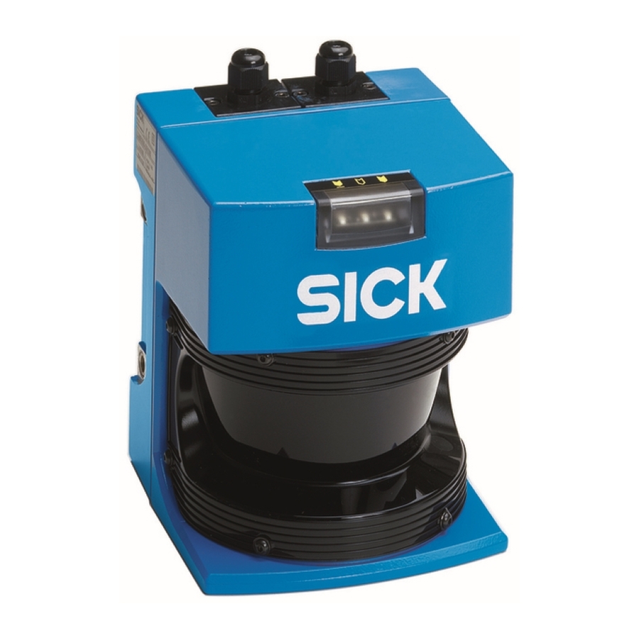
Errors caused by a contaminated front window are indicated via the built-in LEDs (see Table 8-1). Please note: LMS laser scanners are not devices for protecting persons as defined by current machine safety standards. © SICK AG · Division Auto Ident · Germany · All rights reserved 8 008 970/06-2003... - Page 5 12 Overview of LMS variants Fig. 2-1: LMS 200 Fig. 2-2: LMS 220 Fig. 2-3: LMS 291 Fig. 2-4: LMS 221 Fig. 2-5: LMS 211 8 008 970/06-2003 © SICK AG · Division Auto Ident · Germany · All rights reserved...
-
Page 6: Operating Principle
0.5° Spot spacing for angular resolution of 0.25° Spot diameter LMS 211/221/291 Spot diameter LMS 200/220 Range [m] Fig. 3-2: Spot sizes/spot spacing © SICK AG · Division Auto Ident · Germany · All rights reserved 8 008 970/06-2003... -
Page 7: Conditions Of Use/Range
Steel, rust-free shiny 120…150% Steel, very shiny 140…200% Reflectors > 2000% Range [m] Fig. 4-1: LMS 200/LMS 220 Range in relation to object reflectivity 8 008 970/06-2003 © SICK AG · Division Auto Ident · Germany · All rights reserved... -
Page 8: Reflectivity In Fog
50 m 100 m 200 m 500 m Range [m] Fig. 4-3: LMS 211 – relationship between reflectivity and range in fog 8 008 970/06-2003 © SICK AG · Division Auto Ident · Germany · All rights reserved... -
Page 9: The „Blanking" Curve
Fig. 4-6: Relationship between the usable range and reliably detected object diameter, e.g. the LMS switches if it loses the contour in 17 m with a object diameter of 0.3 m. 8 008 970/06-2003 © SICK AG · Division Auto Ident · Germany · All rights reserved... -
Page 10: Areas Of Use
*) 100°/180° 180° 100°/180° 100°/180° max. no of measured values 4x1°-values, interlaced *)symmetrical, from the middle Angular resolution is set using a software telegram. © SICK AG · Division Auto Ident · Germany · All rights reserved 8 008 970/06-2003... -
Page 11: Area Monitoring/Detection
100° Fig. 5-1: Direction of transmission for Fig.5-2: Direction of transmission for LMS 211 scanners LMS 200, LMS 220, LMS 221, LMS 291 scanners 8 008 970/06-2003 © SICK AG · Division Auto Ident · Germany · All rights reserved... -
Page 12: Mounting
(motor flap) must be screwed in (to maintain the enclosure rating). LMS 211 dust shield ± 7,5° ± 7,5° Fig. 6-1: Mounting set for LMS 220/LMS 211/LMS 221 Fig. 6-2: Sunshade (examples) © SICK AG · Division Auto Ident · Germany · All rights reserved 8 008 970/06-2003... - Page 13 Fig. 6-3: Attachment set for mast mounting of LMS 220/LMS 211/LMS 221 Fig. 6-4: Mounting set for LMS 200/LMS 291 Fig. 6-5: Weather protection for LMS 220/LMS 221 8 008 970/06-2003 © SICK AG · Division Auto Ident · Germany · All rights reserved...
-
Page 14: Lms 211/Lms 220/Lms 221 Electrical Installation
(motor- RS 422 flap) 2x2 TP host computer/ heater sensor control cabinet (motor- RS 422 flap) Fig. 7-2: Wiring with external data processing © SICK AG · Division Auto Ident · Germany · All rights reserved 8 008 970/06-2003... -
Page 15: Motor Flap For The Lms 211
If the motor flap is not in use, or is no longer in use, the connection socket must be cov- ered with the cap (to maintain the enclosure rating). 8 008 970/06-2003 © SICK AG · Division Auto Ident · Germany · All rights reserved... -
Page 16: Lms 211/Lms 221 Electrical Connection
RS 232 RS 232 switching outputs restart scanner heater RS 422 external +24V +24V Fig. 7-6: LMS 211/LMS 221/LMS 220 wiring © SICK AG · Division Auto Ident · Germany · All rights reserved 8 008 970/06-2003... -
Page 17: Lms 211/Lms 221 Electrical Connection With Relay Output
Output OUT C is designed to act as a regular field output but automatically assumes an error signalling function if there is a break (see also Chap. 8.3.3). 8 008 970/06-2003 © SICK AG · Division Auto Ident · Germany · All rights reserved... -
Page 18: Lms 200/Lms 291 Electrical Installation
Furthermore, please note that regarding ESD protection the LMS should only be operated with the plug modules mounted. Fig. 8-2: Scanner with plug-in connection boxes © SICK AG · Division Auto Ident · Germany · All rights reserved 8 008 970/06-2003... -
Page 19: Lms 200/Lms 291 Electrical Connection
TxD– – – – jumpered – RS 422 – Fig. 8-4: Interface plug jumper soldered soldered Fig. 8-5: Convertible interface plug (RS 422 pre-selected) 8 008 970/06-2003 © SICK AG · Division Auto Ident · Germany · All rights reserved... -
Page 20: Cable Entry In Plug Module
50% on/50% off Switching signal on OUT C alternatively as field output or error signal (higher priority) Tab. 8-1: Functions of the indicator lights © SICK AG · Division Auto Ident · Germany · All rights reserved 8 008 970/06-2003... -
Page 21: Synchronisation Of Two Laser Scanners
The scanner data cables must not be wired through the connection box. Observe instruc- tions in the Technical Description when selecting the type of interface and acceptable cable lengths. 8 008 970/06-2003 © SICK AG · Division Auto Ident · Germany · All rights reserved... -
Page 22: Commissioning Synchronisation
PG 16 screw joints. If enclosure rating IP 65 is required, the appropriate PG screw joints are to be used (Tradeware). Fig. 9-2: View into connection box for synchronisation © SICK AG · Division Auto Ident · Germany · All rights reserved 8 008 970/06-2003... -
Page 23: Heating Plate For The Lms 200/Lms 291
Heating-up time at –12 °C max. 20 min. –20…+70 °C Storage temperature Dimensions see Fig. 10-1 Weight approx. 1.2 kg Table 10-1: Heating plate technical data 8 008 970/06-2003 © SICK AG · Division Auto Ident · Germany · All rights reserved... - Page 24 Heating plate Chapter 10 Technical Description LMS 2… Laser Measurement System Fig. 10-1: Mounting the heating plate on the LMS 200/LMS 291 © SICK AG · Division Auto Ident · Germany · All rights reserved 8 008 970/06-2003...
-
Page 25: Weather Protection For The Lms 220/Lms 221
Weather protection Heating plate Technical Description Chapter 10 LMS 2… 101,7 Fig. 10-2: Dimensions of weather protection for LMS 220/LMS 221 8 008 970/06-2003 © SICK AG · Division Auto Ident · Germany · All rights reserved... -
Page 26: Dimensional Drawings
Dimensional drawings Chapter 11 Technical Description LMS 2… Laser Measurement System Dimensional drawings Fig. 11-1: LMS 211 dimensions © SICK AG · Division Auto Ident · Germany · All rights reserved 8 008 970/06-2003... - Page 27 Dimensional drawings Technical Description Chapter 11 LMS 2… Fig. 11-2: LMS 211 dimensions with dust prevention shield 8 008 970/06-2003 © SICK AG · Division Auto Ident · Germany · All rights reserved...
- Page 28 Dimensional drawings Chapter 11 Technical Description LMS 2… Laser Measurement System Fig. 11-3: LMS 220/LMS 221 dimensions © SICK AG · Division Auto Ident · Germany · All rights reserved 8 008 970/06-2003...
- Page 29 Dimensional drawings Technical Description Chapter 11 LMS 2… Fig. 11-4: LMS 200/LMS 291 dimensions 8 008 970/06-2003 © SICK AG · Division Auto Ident · Germany · All rights reserved...
- Page 30 Dimensional drawings Chapter 11 Technical Description LMS 2… Laser Measurement System Fig. 11-5: Mounting sets 1, 2, and 3 dimensions © SICK AG · Division Auto Ident · Germany · All rights reserved 8 008 970/06-2003...
- Page 31 Dimensional drawings Technical Description Chapter 11 LMS 2… Fig. 11-6: LMS 211/LMS 221/LMS 220 mounting set 8 008 970/06-2003 © SICK AG · Division Auto Ident · Germany · All rights reserved...
- Page 32 3rd axis without 3rd axis weight without 3rd axis 4,8 kg, with 3rd axis 6,3 kg Fig. 11-7: LMS 200 fine adjustment mounting set © SICK AG · Division Auto Ident · Germany · All rights reserved 8 008 970/06-2003...
-
Page 33: Overview Of Lms Variants
• measured values for partitioned sector • averaged measured values for partitioned sector (up to 250 scans) Table 12-2: Overview of scanner functions 8 008 970/06-2003 © SICK AG · Division Auto Ident · Germany · All rights reserved... -
Page 34: Technical Data
IEC 68 part 2-29, 10 g/16 ms Shock absorbers are recommended for heavy vibration and impact demands (e.g. AGV applications). Table 13-1: Technical data © SICK AG · Division Auto Ident · Germany · All rights reserved 8 008 970/06 -2003... -
Page 35: Order Numbers
Interface cable, connection LMS – PC for setting parameters/configuration 2019561 RS 232/422, cable length 5 m Purging air fan on request Table 14-1: Order numbers (continued on next page) 8 008 970/06-2003 © SICK AG · Division Auto Ident · Germany · All rights reserved... - Page 36 LMI 101 (measuring bulk materials) 7044000 LMI 200 evaluation and control unit for measurement applications 1016761 Customer-specific evaluations on request Table 14-1 (cont.): Order numbers © SICK AG · Division Auto Ident · Germany · All rights reserved 8 008 970/06-2003...
-
Page 37: Glossary Of Terms
The range of validity of the reference contour can be set as desired. This function can also be used to prevent sabotage. 8 008 970/06-2003 © SICK AG · Division Auto Ident · Germany · All rights reserved... -
Page 38: Ec Declaration Of Conformity
EC Declaration Chapter 15 Technical Description LMS 2… Laser Measurement System Fig. 15-1: Reproduction of the EC Declaration of Conformity, page 1 (reduced in size) © SICK AG · Division Auto Ident · Germany · All rights reserved 8 008 970/06-2003... - Page 39 EC Declaration Technical Description Chapter 10 LMS 2… Fig. 15-2: Reproduction of the EC Declaration of Conformity, page 2 (reduced in size) 8 008 970/06-2003 © SICK AG · Division Auto Ident · Germany · All rights reserved...
- Page 40 Received from your SICK partner: SICK AG Auto Ident Nimburger Straße 11 79276 Reute Germany www.sick.com...
Need help?
Do you have a question about the LMS 200 and is the answer not in the manual?
Questions and answers