
Subscribe to Our Youtube Channel
Related Manuals for Westermo TD-32/485


Summary of Contents for Westermo TD-32/485
- Page 1 INSTALLATION MANUAL 6178-2203 Galvanic Transient Isolation Protection Approved Tele modem V.32bis www.westermo.se...
-
Page 3: Table Of Contents
Safety ......................................Specifications .................................. Installation ..................................RS-232/V.24 Connections ........................... Line Connection ................................ Typical TD-32 Line Connections ..................... TD-32/485 (RS-422/485 interface) ....................DIP Switch Setup 10–13 ............................ LED Status Indicators ........................... DTE Command Lines ............................ AT Command Set 15–34 ............................ Result Codes ................................ -
Page 4: Introduction
Introduction The Westermo TD-32 is an industrialised dial and leased line modem. This modem has been devel- oped to be used in industrial applications and has some features you would not expect to find on a normal modem. Terminal data rates of up to 57.6 kbit/sec can be handled using data compression and error correc- tion. -
Page 5: Specifications
Specifications Modulation CCITT V.32bis, 4 800 till 14 400 bit/s CCITT V.32, 4 800/9 600 bit/s CCITT V.22bis, 2 400 bit/s CCITT V.22, Bell 212A, 1200 bit/s CCITT V.21, Bell 103, 300 bit/s Dial up Tone signals DTMF Settings AT-commands & switches Transmission Asynchronous &... -
Page 6: Installation
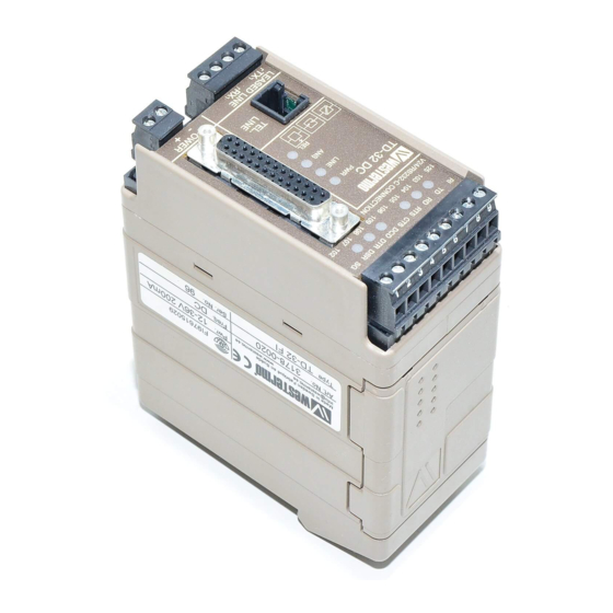
Installation The modem should be con- nected in the following way: Screw-block for Power connection is made RS-232/V.24 connection through screw-block at bottom Light right corner. emitting For 115V AC or 230V AC it is a diodes 3-pole connector, and for 12–36 or 36–60V DC a 2-pole connec- tor. -
Page 7: Rs-232/V.24 Connections
RS-232/V.24 Connections Pin outs for the 25-pole D-sub and 9-pole screw terminal: 25-pos. Screw Direction Name Description D-sub Terminal DCE-DTE - - - Protective earth ← Transmit data Receive data ← Request to send Clear to send Modem ready - - - Signal ground Data carrier detect Continuous high... -
Page 8: Typical Td-32 Line Connections
Typical TD-32 line connections 4-position screw terminal Leased line 2-wire 4-position screw terminal Leased line 4-wire Handshaking The TD-32 is delivered with a factory setting for “hardware hand- shake” with RTS-CTS which means that if only TX, RX and GND are connected no data will be sent on the receiving modem’s RS-232 connection unless RTS is high. -
Page 9: Td-32/485 (Rs-422/485 Interface)
TD-32/485 (RS-422/485 interface) TD-32/485 As an option the TD-32 can be supplied with an RS-422/485 interface. This product is referred to as the TD-32/485. On the TD-32/485 the RS-232/V.24 connection on the screw WIRE terminal on upper front side of the unit has been replaced with... -
Page 10: Dip Switch Setup
DIP Switch Setup for Dial-up and Leased Line Disconnect power before changing DIP-switches. Use ESD-protection when changing switches. The DIP-switches can be used to provide the following settings. The DIP-Switches are underneath the top lid of the modem. Non defined switches will be in off position. Switch 1 Related AT-commands... - Page 11 Switch 2 Related AT-commands 2–8 are not used 1 2 3 4 5 6 7 8 For use of SW2:2 to 7 1 2 3 4 5 6 7 8 Asynchronous communication 1 2 3 4 5 6 7 8 Synchronous, external clock.
- Page 12 Switch 4 (Serial speed and format) Related AT-commands Automatic detection of serial speed and format 1 2 3 4 5 6 7 8 300 bit/s 1 2 3 4 5 6 7 8 600 bit/s 1 2 3 4 5 6 7 8 1 200 bit/s 1 2 3 4 5 6 7 8 2 400 bit/s...
-
Page 13: Led Status Indicators
Switch 5 (line modulation) Related AT-commands Used saved parameters 1 2 3 4 5 6 7 8 V.21; 300 bit/s (ATF1) 1 2 3 4 5 6 7 8 (ATF4) V.22; 1 200 bit/s 1 2 3 4 5 6 7 8 V.22bis;... -
Page 14: Dte Command Lines
DTE Command Lines In order to send commands to the modem, a prefix must be entered before the actual command(s). This prefix is the ASCII string ‘AT’, which is an abbreviation for attention. Commands may be entered in either upper or lowercase characters. The only exception is the prefix ‘AT’;... -
Page 15: At Command Set
Description of commands The modem can be configured and controlled with the AT-commands listed below. A/ – Re-execute command This command differs from the others since it will not be preceded by ”AT” and also not terminated by ENTER. A – Answer The modem will wait for a carrier for the time that was specified in S7. - Page 16 &Bn – DTR Dial Option This command enables the modem to dial a number stored with &Zn=number when the DTR signal goes from inactive to active signal level. &B0 No automatic call with DTR. (Default) &B1 Call on DTR. Please also refer to AT&Z, AT&D \Bn –...
- Page 17 %C – Enable/disable data compression Enables or disables data compression negotiation. The modem can only perform data compression on an error corrected link. The parameter value is written to S41 bit 0 and 1. Disables data compression. Resets S41 bit 1 to 0. Enables MNP 5 data connection.
- Page 18 &Dn – DTR Option This command uses the incoming signal DTR to do different things, depending on n. The value is written to S21 bit 3 and 4. &D0 DTR drop is interpreted according to the setting as follows: (Default) If &Q0, &Q5 or &Q6 is set: DTR is ignored (assumed ON).
- Page 19 %Dn – Setting the sensitivity of the receiver This command sets if the modem will disconnect when the signal level on the line is below the normal value (approx. –43 dBm) or the value entered in S24, the level can only be set to values above –43 dBm.
- Page 20 Fn – Select Line Modulation This command selects which type of modulation will be used on the phone line. If this parameter is set to something else than F0, the line speed will be fixed. The value is written to register S31 bit 1. Either the ATF command is used or the ATN command and register S37 but not both methods simultaneously.
- Page 21 &F – Restore factory configuration The command restores the original factory setting of all parameters. These will only be used, until a restart of the modem occurs. When the modem restarts it will use the settings previously stored in profile 0 or profile 1, depending on the 8Yn command. If one wishes to keep the default values to next restart, use the command &W directly after the &F.
- Page 22 Hn – Disconnection The command makes the modem either connect to or disconnect from the line. Disconnection ”on-hook”. Connection ”off-hook”. Please also refer to S7 *Hn – MNP10 connection speed This command controls the initial line speed during connection, between two MNP10 modems. The value is written to S28 bit 6 and 7.
- Page 23 \Kn – Break Control This command controls the response of the modem to a break signal received from the terminal equipment, from the remote modem or through the \B command. The modem can respond in 3 differ- ent ways depending on the state of the modem. The value is written to S40 bit 3,4 and 5. The first case is where the modem receives a break signal from the local terminal and the modem is in communication mode: Enter command mode, no break signal is sent to the remote modem.
- Page 24 Ln – Speaker Volume The modem sets the speaker volume depending on the value used according to the following list. The value is written to register S22 bit 0 and 1. Speaker off. Low volume. (Default) Medium volume. High volume. Please also refer to ATM %L –...
- Page 25 &Mn – Asynchronous/Synchronous Mode Selection This command determines how the DTR signal will be used. &M0 Selects direct asynchronous communication. The value 000 is written to S27 bit 3, 1 and 0 &M1 Selects synchronous communication mode with asynchronous communication with the modem in command mode.
- Page 26 \Nn – Operating Mode This command determines which error correcting mode will be used during a link negotiation. Normal speed buffered mode. (Forces &Q6) Selects direct mode and is equivalent to &M0, &Q0 (Forces &Q0) In this mode RS-232/V.24 data is directly connected to the data pump, which results in the lowest possible delay time.
- Page 27 &Qn – Asynchronous/Synchronous Mode This command is an extension of the &M command and is used for controlling permitted connection modes. It is used together with S36 and S48. When the &Q0 to &Q4 command is issued, the subsequent connect message will report the line speed regardless of the W command and S95 settings.
- Page 28 Sn – Read or Write Values to S-register This command is used for selecting an S-register as default, for reading the value stored in the register or for storing a new value. The values in the S-registers must be within the permitted interval for each register, otherwise the command that sets the value will be reported with ERROR.
- Page 29 \S – Report Active Configuration The command reports a list of parameters in the active configuration mode. For example: AT\S CMD DESCRIPTION / OPTION CMD DESCRIPTION / OPTION CMD DESCRIPTION / OPTION COUNTRY..SWE &A CHR ABORT OPT..NO NEG. SPEED..HIGH DTE BPS..9600 &B DTR DIAL OPTION..NO RINGS TO ANS..002...
- Page 30 &Tn – Test and Diagnostics The modem will perform different tests and diagnostic functions according to the parameter supplied with this command. Tests can only be run when the modem is in non-error corrective asynchronous mode (normal or direct mode). To terminate a test in progress the escape sequence must be sent to the modem first, except for test 7 and 8.
- Page 31 &V – Display Current Configuration and Stored Profiles This command returns the active configuration, the two stored profiles and the first four saved phone numbers to the terminal. Example: AT&V ACTIVE PROFILE: B0 E1 L1 M1 N1 Q0 T V1 W0 X4 Y0 &C0 &D0 &G0 &J0 &K3 &Q5 &R1 &S0 &T5 &X0 &Y0 S00:002 S01:000 S02:043 S03:013 S04:010 S05:008 S06:010 S07:050 S08:002 S09:006 S10:014 S11:095 S12:050 S18:000 S25:005 S26:001 S36:007 S37:000 S38:020 S44:020 S46:138 S48:007 S95:000...
- Page 32 &Wn – Save Current Configuration Saves the current (active) configuration, including S-registers, in one of the user profiles in NVRAM. The current configuration is replaced with the one stored in one of the user profiles when the modem is re-started or when the Zn command is sent to the modem. &W0 Store the current configuration in profile 0.
- Page 33 &Xn – Select Synchronous Clock Source This command selects the source of the transmit clock at synchronous communication. In asynchro- nous mode the clock is completely turned off. In synchronous mode the clock is turned on with the frequency of 1200 Hz or faster, depending on the speed selected for communication. &X0 Selects internal clock.
- Page 34 Zn – Soft Reset and Restore Profile The modem performs a soft reset and restores the configuration profile according to the parameter supplied. If no parameter is given after Z, the configuration in profile 0 will be used. Soft reset. The configuration in profile 0 will be used Soft reset.
-
Page 35: Result Codes
Result Codes When a command is sent from the terminal the modem replies with a result code. The reply may be either in Long Form i.e. text (V1) or in Short Form, i.e. a two digit code (V0). The result code in Long Form is followed by <CR><LF>... -
Page 36: S-Registers
S-registers Below follows a description of the S-registers and its different components. Note that some parameters can not be changed due to local PTT-regulations in different countries. Where nothing else is stated the registers are stored by using the AT&W command. Some registers are read only registers and can not be changed from the DTE. - Page 37 S9 – Carrier Detect Response Time Sets the time that the carrier must be present before a connection is established. Default 6 {1..255} (1/10 sec). S10 – Lost Carrier To Hang Up Delay Sets the length of time that the modem waits before hanging up after a loss of carrier. When register S10 is set to 255, the modem functions as if a carrier were always present.
- Page 38 S16 – General Bit Mapped Test Options Status (&T) (Read only register, not stored with &W) Interval Default Description – Local analogue loopback: 0-Disabled 1-Enabled (AT&T1) 0..1 Not used 0..1 Local digital loopback: 0-Disabled 1-Enabled (AT&T3) 0..1 RDL Status: 0-Modem not in RDL 1-RDL läge (AT&T4) 0..1 RDL statusrequest:...
- Page 39 S21 – General Bit Mapped Options Status (Read only register) Interval Default Description 0..1 Set by AT&J only for compatibility 0..1 Reserved 0..1 CT106 (CTS) Behaviour: 0-AT&R0 vald 1-AT&R1 vald 3..4 0..3 CT108 (DTR) Behaviour: 0-AT&D0 selected 1-AT&D1 selected 2-AT&D2 selected 3-AT&D3 selected 0..1 Reserverad...
- Page 40 S23 – General Bit Mapped Options Status (Read only register) Interval Default Description 0..1 Enables RDL: 0-Not allowed (AT&T5) 1-Allowed (AT&T4) 1..3 0..7 Current speed on DTE (bps): 0-300 1-600 2-1 200 3-2 400 4-4 800 5-9 600 6-19 200 7-38 400 or higher 4..5 0..3...
- Page 41 S27 – Bit Mapped Option Status (Read only) Interval Default Description 0..1,3 0..3,0..1 Synchronous/Asynchronous selection: 0.0-AT&M0 or AT&Q0 1.0-AT&M1 or AT&Q1 2.0-AT&M2 or AT&Q2 3.0-AT&M3 or AT&Q3 0.1-AT&Q4 1.1-AT&Q5 2.1-AT&Q6 0..1 Reserved 4..5 0..2 Synchronous clock selection: 0-Internal clock (AT&X0) 1-External clock (AT&X1) 2-Slave clock (AT&X2) 0..1...
- Page 42 S31 – Bit Mapped Option Status (Read only) Interval Default Description – – Reserved 0..1 Automatic line setting: 0-ATN0 1-ATN1 2..3 0..2 Error correction messages: 0-Reports only speed on serial port (ATW0) 1-Reports line speed and speed on serial port (AT&W1) 2-Reports only line speed (ATW2) 4..7 –...
- Page 43 S38 – Delay Before Forced Hang Up (Not stored with the AT&W command) This register specifies the delay between the modem’s receipt of the H command to disconnect (or ON-to-OFF transition of DTR if the modem is programmed to follow the signal), and the disconnect operation.
- Page 44 S41 – Bit mapped register (Read Only Register) Interval Default Description 0..1 0..3 Compression selection: 0-No compression (AT%C0) 1-MNP5 (AT%C1) 2-V.42bis (AT%C2) 3-MNP5 or V.42bis (AT%C3) 0..1 Automatic line quality and fall back/fall forward: 0-Line quality and fall back/fall forward disabled (AT%E0) 1- Line quality and fall back/fall forward enabled (AT%E1)
- Page 45 S95 – Extended Result Codes Interval Default Description 0..1 Display CONNECT speed message: 1-CONNECT with speed enabled 0..1 Addition of ARQ: 1-ARQ text is added to the message 0..1 Display of CARRIER message: 1-CARRIER text is added to the message 0..1 Display of PROTOCOL message: 1-PROTOCOL text is added to the message...
-
Page 46: Application Examples
Example: Several commands can be stacked on each command-line. For example: ATEQ1\N4D12345 can be used instead of: ATE0 ATQ1 AT\N4 ATD12345 with the same result. To use MINICALL (Pager systems) Waits for tone in maximum 60 seconds. ATS6=60 Dot gives disconnection. ATD^0746xxxxxxW0yyyyyyyy#,. - Page 47 Frequently used settings for PLC-systems and industrial applications Most PLC-systems and other industrial applications where modems are used require the same changes to the standard settings. The most commonly encountered problems concern speed, parity and control signals from the connected equipment. Speed and parity are changed with the switches under the cover in block SW4.
- Page 48 Dial up with hardware signalling External signal Dial up can be made by applying an external signal to the DTR-pin in the RS-232/V.24 contact. A typical application is an alarm signal from a PLC or another relay contact. The modem reacts on the first rising edge which means that one pulse is sufficient. The signal level should be in compliance with the RS-232/V.24 standard.
- Page 49 Leased line applications Leased line connections can be done using either 2-wire or 4-wire. When renting a 4-wire line from a telephone company one pair of cables for transmission and one pair for reception are usually provided. The maximum transmission distance depends on the attenuation of the line. The maximum value is the- oretically 30 dBm.
-
Page 50: Glossary
Glossary ASCII A binary code system which defines 128 characters using different combinations of 1s and 0s. ASCII = American Standard Code for Information Interchange. Asynchronous Data Transmission where the characters are transmitted one at a time, starting with a start bit and ending with a stop bit. - Page 51 Automatic Repeat reQuest. When incorrect data is detected a request to retransmit the data is made to the remote modem. Data Compression technique used by modems rather than MNP5, because it offers V.42bis. better transmission on already compressed data. Data Rate In modems this is often different to the baud rate.
- Page 52 Modem Acronym of the words modulator and demodulator. Modulates or transforms the signal from computer equipment into electrical or acoustic signals for transmission. The receiver has a similar modem which retransforms the signal, demodulation. Modem Modulation Standards V.21 300 bit/s, similar to Bell 103 V.23 1 200/75 bps Split speed line V.23hdx...
- Page 53 RS-232/V.24 Signals Transmitted Data. Data going from DTE to DCE. Received Data. The Data going from DCE to DTE. Request to Send. Hardware handshake generated by the DTE to determine if the DCE is ready to receive data. Expected response is from the CTS line. Clear To Send.
- Page 54 OWN COMMENTS ................................................................................................................................................................................................................................................................................................................................................................................................................................................................................................................................................................................................................................................................6178-2203...
- Page 56 Power supply Dip-switch PROM Memory Isolated power supply Westermo Teleindustri AB • S-640 40 Stora Sundby Tel 016 612 00 Fax 016 611 80 E-mail: info@westermo.se • Westermo Web site: www.westermo.se Dotterbolag Westermo Data Communications Ltd Westermo Data Communications GmbH Unit 14 Talisman Business Centre •...
Need help?
Do you have a question about the TD-32/485 and is the answer not in the manual?
Questions and answers