Table of Contents
Advertisement
Quick Links
Advertisement
Table of Contents

Subscribe to Our Youtube Channel
Related Manuals for Westermo TD-23


Summary of Contents for Westermo TD-23
- Page 1 TD-23 Leased Line V.23 Modem Multidrop applications...
- Page 2 6600-2204...
-
Page 3: General Information
Under no circumstances shall Westermo be responsible for any loss of data or income or any special, incidental, and consequential or indirect damages howsoever caused. -
Page 4: Care Recommendations
Do not use or store the unit in dusty, dirty areas, connectors as well as other mechanical part may be damaged. If the unit is not working properly, contact the place of purchase, nearest Westermo distributor office or Westermo Tech support. -
Page 5: Product Disposal
Product disposal This symbol means that the product shall not be treated as unsorted municipal waste when disposing of it. It needs to be handed over to an applicable collection point for recy- cling electrical and electronic equipment. By ensuring this product is disposed of correctly, you will help to reduce hazardous substances and prevent potential negative consequences to both environment and human health, which could be caused by inappropriate disposal. -
Page 6: Simplified Eu Declaration Of Conformity
Simplified EU declaration of conformity Hereby, Westermo declares that the equipment is in compliance with EU directives. The full EU declaration of conformity and other detailed information are available at the respective product page at www.westermo.com. Agency approvals and standards compliance... - Page 7 Type tests and environmental conditions Electromagnetic Compatibility Phenomena Test Description Test levels EN 61000-4-2 Enclosure contact ± 6 kV Enclosure air ± 8 kV RF field AM IEC 61000-4-3 Enclosure 6 V/m 80% AM (1 kHz) 2000 – 2700 MHz modulated 10 V/m 80% AM (1 kHz), 80 –...
- Page 8 A general calculation allows 16 units over a distance of up to 25 km (15.5 miles). TD-23 is intended for mounting on a 35 mm DIN-rail, where the modem is attached and locked in a single action.
-
Page 9: Functional Description
Functional description Block diagram Modulated data Line relay 2 or 4-wire Selectable Selectable output level input sensitivity Modem Analog filter Frequency Frequency DIP-switches modulation demodulation Processor Modem Data Data chip buffer buffer control RTS CTS DCD RD TD TD RD Relay RS-232 RS-422/485... -
Page 10: Interface Specifications
Interface specifications Power LV Rated voltage 12 to 48 VDC 12 to 27 VAC Operating voltage 10 to 60 VDC 10 to 30 VAC Rated current 125 mA @ 12 VDC 50 mA @ 24 VDC 28 mA @ 48 VDC 125 mA @ 12 VAC 50 mA @ 24 VAC 25 mA @ 32 VAC... - Page 11 RS-422/485 Electrical specification EIA RS-485 2-wire or 4-wire twisted pair Data rate 300 bit/s – 1200 bit/s Data format 7 or 8 data bits, Odd, even or none parity, 1 or 2 stop bits; Σ 9-12 bits Protocol Transparent Retiming Turn around time 4.2 ms (half duplex) ≤...
- Page 12 Relay (optional) Rated voltage Up to 48 VDC Operating voltage Up to 60 VDC Contact rating 50 mA @ 48 VDC 8 Ω Contact resistance ≤ 3 m, depending on data rate and cable type Transmission range Function The output follows the transmit carrier, I.e. output shorted when carrier is ON.
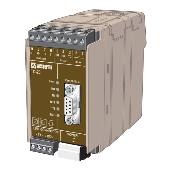
- Page 13 Location of Interface ports, LED’s and DIP-switches TD-23 HV RS-422/485 Product 9-pos. Direction* Description marking R+ (A’) Receive No 9 RS-422/485 4-wire R– (B’) Receive No 8 R– RS-422/485 4-wire T+ (A) Transmit RS-422/485 4-wire No 7 T+/R+ (A/A’) Transmit/Receive...
- Page 14 Location of Interface ports, LED’s and DIP-switches TD-23 LV RS-422/485 Product 9-pos. Direction* Description marking R+ (A’) Receive No 9 RS-422/485 4-wire R– (B’) Receive No 8 R– RS-422/485 4-wire T+ (A) Transmit RS-422/485 4-wire No 7 T+/R+ (A/A’) Transmit/Receive...
- Page 15 LED Indicators Status Description In service Power Out of service Data transmitted on the RS-232 or RS-485 port Receive data No data transmitted on the RS-232 or RS-485 port Data received on the RS-232 or RS-485 port Transmit data No data received on the RS-232 or RS-485 port RTS signal active on the RS-232 port Request to send...
-
Page 16: Dip Switch Settings
DIP-switch settings Before DIP-switch settings: Prevent damage to internal electronics from electrostatic discharges (ESD) by dis- charging your body to a grounding point (e.g. use of wrist strap). NOTE DIP-switch alterations are only effective after a power on. S1 DIP-switch Selection of transmission level 3 dBm –9 dBm... - Page 17 Selection of minimum level, DCD detection specifies the minimum power level the receiver can handle. With the receiver having a dynamic range of 30 dBm, this means that with the level set to –15 dBm the TD-23 will pick up signals in the range –15 dBm to –45 dBm.
- Page 18 S2 DIP-switch Selection of 2/4 wire RS-422/485 side Deactivate 2-wire 4-wire RS-422/485 1 2 3 4 5 6 7 8 1 2 3 4 5 6 7 8 1 2 3 4 5 6 7 8 All RS-422/485 lines should be terminated at the end-points. The RS-422/485 interface also has a fail-sate circuit which forces a non-active line into idle state.
- Page 19 S3 DIP-switch RS-422/485 termination No termination 2-wire termination with 4-wire termination with failsafe; or failsafe failsafe; T+/R+ and T– /R– R+ and R– 1 2 3 4 1 2 3 4 1 2 3 4 Factory settings 1 2 3 4 1 2 3 4 5 6 7 8 1 2 3 4 5 6 7 8 6600-2204...
- Page 20 Slave unit Termination recommendations The RS-422/485 line must be terminated. In the TD-23 the termination is combined with fail-safe functionality. For that reason it is important that the termination is used not to get undefined states when the bus is in three state condition.
- Page 21 Mounting This unit should be mounted on 35 mm DIN-rail, which is horizontally mounted inside an apparatus cabinet, or similar. Snap on mounting, see figure. 10 mm * (0.4 inches) Cooling 25 mm This unit uses convection cooling. To avoid obstructing the airflow around the unit, use the following spacing rules.
-
Page 22: Application Examples
Application examples RS-232, 2-wire connection 2-wire twisted pair DIP-switch setting for both units 1 2 3 4 5 6 7 8 1 2 3 4 5 6 7 8 1 2 3 4 6600-2204... - Page 23 Multidrop application 1 2 3 4 5 6 7 8 RS-485 1 2 3 4 5 6 7 8 1 2 3 4 Master 1 2 3 4 5 6 7 8 1 2 3 4 5 6 7 8 1 2 3 4 5 6 7 8 1 2 3 4 5 6 7 8 1 2 3 4...
- Page 24 Westermo • SE-640 40 Stora Sundby, Sweden Tel +46 16 42 80 00 Fax +46 16 42 80 01 E-mail: info@westermo.com www.westermo.com REV.H 6600-2204 2019-01 Westermo Network Technologies AB, Sweden...
Need help?
Do you have a question about the TD-23 and is the answer not in the manual?
Questions and answers