
Subscribe to Our Youtube Channel
Related Manuals for Westermo TD-33


Summary of Contents for Westermo TD-33
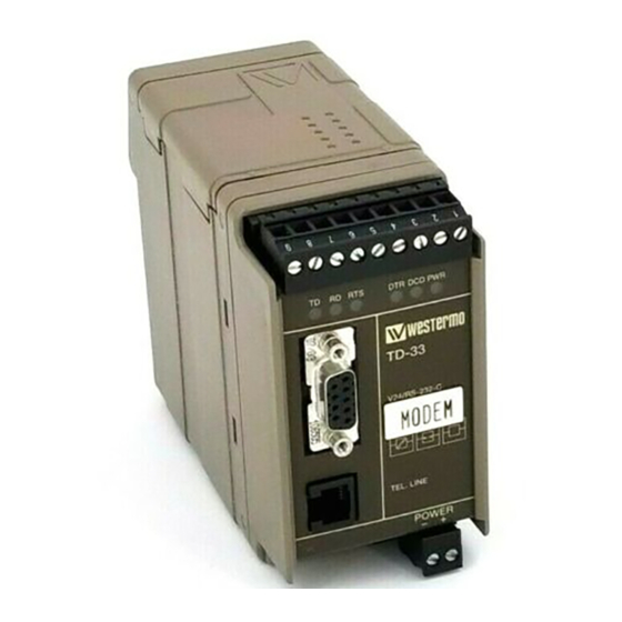
- Page 1 INSTALLATION MANUAL 6179-2201 Galvanic Transient Balanced Isolation Protection Transmission Approved Tele Modem V.90/K56flex™ or V.34 www.westermo.se...
-
Page 3: Table Of Contents
Table of Contents Introduction ..................................Safety ......................................Specifications .................................. Installation ..................................RS-232/V.24 Connections ........................... Line Connection ................................ Typical TD-33 Line Connections ..................... DIP Switch Setup ..............................LED Status Indicators ............................AT Commands 8–20 ............................... Result Codes 21–23 ..............................S-Registers 24–31 ................................. -
Page 4: Introduction
Introduction Congratulations for purchasing TD-33, probably the most robust modem device available on the mar- ket. You have just got a high quality product, and with the excellent support from Westermo you will certainly not be unsatisfied with this product. -
Page 5: Specifications
Specifications Modulation ITU-T V.90 28.0 up to 56.0 kbit/s K56flex™, 32.0 up to 56.0 kbit/s ITU-T V.34, 2.4 up to 33.6 kbit/s ITU-T V.32bis, 4.8 up to 14.4 kbit/s ITU-T V.32, 4 800/9 600 bit/s ITU-T v.23, 1 200 bit/s ITU-T V.22bis, 2 400 bit/s ITU-T V.22, Bell 212A, 1 200 bit/s ITU-T V.21, Bell 103, 300 bit/s... -
Page 6: Installation
Line connection The telephone line is connected TEL.LINE to the 2-pole RJ-11 connector. 2-wire lines are connected to the two middle pins (3 & 4) in the RJ-11 plug. Typical TD-33 line connections RJ-11 Telephone Telephone plug TEL.LINE Exchange Exchange... -
Page 7: Dip Switch Setup
The DIP-switches can be used to provide the following settings. TD RD RTS DTR DCD PWR The DIP-Switches are underneath the top lid of the modem. Non defined switches will be in off position. TD-33 V24/RS-232-C TEL.LINE S1:1-4 Switch 1... -
Page 8: At Commands
AT Commands A – Answer The modem will go off-hook and attempt to answer an incoming call if correct conditions are met. Upon successful completion of answer handshake, the modem will go on-line in answer mode. The modem will enter the connect state after exchanging carrier with the remote modem. If no carrier is detected within a period specified in register S7, the modem hangs up. - Page 9 Dn – Dial This command directs the modem to go on-line, dial according to the string entered and attempt to establish a connection. If no dial string is supplied, the modem will go on-line and attempt the handshake in originate mode. NOTE: If the ATD command is issued before the S1 register has cleared, the modem will respond with the NO CARRIER result code.
-
Page 10: At Commands
Dial pause: the modem will pause for a time specified by S8 before dialing the digits following ”,”. Return to command state. Added to the end of a dial string, this causes the modem to return to the command state after it processes the portion of the dial string preceding the ”;”. - Page 11 When line quality is insufficient, the modem will initiate a rate renegotiation to a lower speed within the V.34/V.32 bis/V.32 (TD-33) modulation speeds. The modem will keep falling back within the current modulation if necessary until the speed reaches 2 400 bit/s (V.34) or 4 800 bit/s (V.32).
- Page 12 Hn – Disconnect (Hang-Up) This command initiates a hang up sequence. H0 The modem will release the line if the modem is currently on-line. Country specific, modulation specific, and error correction protocol specific (S38) processing is handled outside of the H0 command. H1 If on-hook, the modem will go off-hook and enter command mode.For EU models, the modem will return on-hook after a period of time determined by S7.
- Page 13 -Kn – MNP Extended Services Enables or disables conversion of a V.42 LAPM connection to an MNP 10 connection. The parameter value, if valid, is written to S40 bits 0 and 1. -K0 Disables V.42 LAPM to MNP 10 conversion. (Default) -K1 Enables V.42 LAPM to MNP 10 conversion.
- Page 14 V.90 56 000, 54 667, 53 333, 52 000, 50 667, 49 333, 48 000, 46 667, 45 333, 42 667, 41 333, 40 000, 38 667, 37 333, 36 000, 34 667, 33 333, 32 000, 30 667, 29 333, 28 000 B103 Bell 103 300 B212...
- Page 15 Qn – Quiet Results Codes Control The command enables or disables the sending of result codes to the DTE according to the parameter supplied. The parameter value, if valid, is written to S14 bit 2. Q0 Enables result codes to the DTE. (Default) Q1 Disables result codes to the DTE.
- Page 16 \Vn – Single Line Connect Message Enable This command enables or disables the single line connect message format as follows: \V0 Connect messages are controlled by the command settings X, W, and S95. \V1 Connect messages are displayed in the single line format described below subject to the command settings V (Verbose) and Q (Quiet).
- Page 17 &V – Display Current Configuration and Stored Profiles &V - Display Current Configuration and Stored Profiles Reports the current (active) con- figuration, the stored (user) profiles, and the first four stored telephone numbers. The stored profiles and telephone numbers are not displayed if the NVRAM is not operational as detected by the NVRAM test during reset processing.
- Page 18 &V1 – Display Last Connection Statistics Displays the last connection statistics in the following format (shown with typical results): TERMINATION REASON..LOCAL REQUEST LAST TX rate....26 400 BIT/S HIGHEST TX rate..... 26 400 BIT/S LAST RX rate....46 667 BIT/S HIGHEST RX rate.....
- Page 19 &Wn – Store Current Configuration Saves the current (active) configuration (profile), including S-Registers, in one of the two user profiles in NVRAM as denoted by the parameter value. This command will yield an ERROR message if the NVRAM is not operational as detected by the NVRAM test. The current configuration is comprised of a list of storable parameters illustrated in the &V command.
- Page 20 Yn – Long Space Disconnect This command enables/disables the generation and response to long space disconnect. The parameter value, if valid, is written to S21 bit 7. Y0 Disables long space disconnect. (Default) Y1 Enables long space disconnect. In non-error correction mode, the modem will send a long space of four seconds prior to going on-hook.
-
Page 21: Result Codes
Result Codes 0 OK A command line has been executed. 1 CONNECT For X command values specifying no speed reporting, the modem has connected to the line and either the line speed is 300 bit/s and line speed is enabled, or the DTE speed is 300 bit/s and DTE speed reporting is enabled. - Page 22 48 CARRIER 4 800 The modem has connected to the line at 4 800 bit/s and carrier reporting is enabled. (See S95 and Xn.) 49 CARRIER 7 200 The modem has connected to the line at 7 200 bit/s and carrier reporting is enabled. (See S95 and Xn.) 50 CARRIER 9 600 The modem has connected to the line at 9 600 bit/s and carrier reporting is enabled.
- Page 23 153 CARRIER 38 000 The modem has connected to the line at 38 000 bit/s and carrier reporting is enabled. (See S95 and Xn.) 154 CARRIER 40 000 The modem has connected to the line at 40 000 bit/s and carrier reporting is enabled. (See S95 and Xn.) 155 CARRIER 42 000 The modem has connected to the line at 42 000 bit/s and carrier reporting is enabled.
-
Page 24: S-Registers
S-registers S0 – Number of Rings to Auto-Answer S0 sets the number of the rings required before the modem automatically answers a call. Setting this register to zero disables auto-answer mode. Range: 0–255 rings Default: 2 S1 – Ring Counter S1 is incremented each time the modem detects a ring signal on the telephone line. - Page 25 S6 – Wait Time before Blind Dialing or for Dial Tone Sets the length of time, in seconds, that the modem will wait for dial tone when encoun- tering a “W” dial modifier before returning NO DIAL TONE result code. (EU models) The modem always pauses for a minimum of 2 seconds, even if the value of S6 is less than 2 seconds.
- Page 26 S10 – Lost Carrier To Hang Up Delay S10 sets the length of time, in tenths of a second, that the modem waits before hanging up after a loss of carrier. This allows for a temporary carrier loss without causing the local modem to disconnect.
- Page 27 S21 – V.24/General Bit Mapped Options Status S21 indicates the status of command options. Default: 52 (34h) (00110100b) Bit 0 Reserved (0) Bit 1 Reserved (0) Bit 2 CTS behavior (&Rn) 0 = CTS tracks RTS (&R0) 1 = CTS always on (&R1) (Default) Bits 3–4 DTR behavior (&Dn) 0 = &D0 selected 1 = &D1 selected...
- Page 28 S24 – Sleep Inactivity Timer S24 sets the length of time, in seconds, that the modem will operate in normal mode with no detected telephone line or DTE line activity before entering low-power sleep mode. The timer is reset upon any DTE line or telephone line activity. If the S24 value is zero, neither DTE line nor telephone inactivity will cause the modem to enter the sleep mode.
- Page 29 S36 – LAPM Failure Control Default: 7 (00000111b) Bits 0–2 This value indicates what should happen upon a LAPM failure. These fallback options are initiated immediately upon connection if S48=128. If an invalid number is entered, the number is accepted into the register, but S36 will act as if the default value has been entered.
- Page 30 S40 – General Bit Mapped Options Status S40 indicates the status of command options. Default: 104 (68h) (01101000b) Bits 0–1 MNP Extended Services (-Kn) 0 = Disable extended services (-K0) (Default) 1 = Enable extended services (-K1) 2 = Enable extended services (-K2) Bit 2 Reserved Bits 3–5 Break Handling (\Kn) 0 = \K0...
- Page 31 S48 – V.42 Negotiation Action The V.42 negotiation process determines the capabilities of the remote modem. However, when the capabilities of the remote modem are known and negotiation is unnecessary, this process can be bypassed if so desired. Range: 0, 7, or 128 If an invalid number is entered, it is accepted into the S-Register, but S48 will act as if 128 has been entered.
-
Page 32: Glossary
Glossary ASCII A binary code system which defines 128 characters using different combinations of 1s and 0s. ASCII = American Standard Code for Information Interchange. Asynchronous Data Transmission where the characters are transmitted one at a time, starting with a start bit and ending with a stop bit. - Page 33 Data Rate In modems this is often different to the baud rate. For instance the Data Rate of V.32bis is 14 400bit/s and the baud rate is 2 400 symbols/second. Direct Mode The Data to be transmitted is sent directly to the data pump (the modem circuit). No compression, error correction or buffering occurs, allowing the data to be transmitted across the link unaltered by the modem.
- Page 34 NVRAM Non Volatile Random Access Memory. Consists most often by an EEPROM (Electronically Eraseable and Programmable memory). Used by the modem to store profile information and numbers even when the unit has no power. Normal Mode A non error corrected connection, where data is buffered. Off Hook Like picking up the receiver.
- Page 36 Westermo Teleindustri AB have distributors in several countries, contact us for further information. Westermo Teleindustri AB • S-640 40 Stora Sundby, Sweden Phone +46 16 612 00 Fax +46 16 611 80 E-mail: info@westermo.se • Westermo Web site: www.westermo.se...
Need help?
Do you have a question about the TD-33 and is the answer not in the manual?
Questions and answers