
Subscribe to Our Youtube Channel
Related Manuals for Westermo TD-23


Summary of Contents for Westermo TD-23
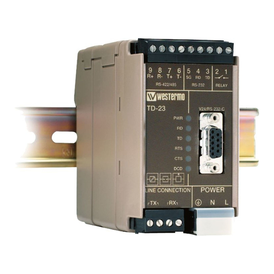
- Page 1 User Guide TD-23 6600-2204 Leased Line V.23 Modem. Multidrop applications www.westermo.com...
-
Page 2: Legal Information
Under no circumstances shall Westermo be responsible for any loss of data or income or any special, incidental, and consequential or indirect damages howsoever caused. -
Page 3: Care Recommendations
Do not use or store the unit in dusty, dirty areas, connectors as well as other mechanical part may be damaged. If the unit is not working properly, contact the place of purchase, nearest Westermo distributor office or Westermo Tech support. -
Page 4: Agency Approvals And Standards Compliance
Agency approvals and standards compliance Type Approval / Compliance EN 61000-6-2, Immunity industrial environments EN 55024, Immunity IT equipment EN 61000-6-3, Emission residential environments FCC part 15 Class B EN 50121-4, Railway signalling and telecommunications apparatus IEC 62236-4, Railway signalling and telecommunications apparatus Safety EN 60950-1, IT equipment FCC Part 15.105 Notice:... -
Page 5: Declaration Of Conformity
Declaration of Conformity 6600-2204... -
Page 6: Type Tests And Environmental Conditions
Type tests and environmental conditions Electromagnetic Compatibility Phenomena Test Description Test levels EN 61000-4-2 Enclosure contact ± 6 kV Enclosure air ± 8 kV RF field AM IEC 61000-4-3 Enclosure 10 V/m 80% AM (1 kHz), 80 – 1000 MHz modulated 20 V/m 80% AM (1 kHz), 80 –... - Page 7 A general calculation allows 16 units over a distance of up to 25 km (15.5 miles). TD-23 is intended for mounting on a 35 mm DIN-rail, where the modem is attached and locked in a single action.
-
Page 8: Functional Description
Functional description Block diagram Modulated data Line relay 2 or 4-wire Selectable Selectable output level input sensitivity Modem Analog filter Frequency Frequency DIP-switches modulation demodulation Processor Modem Data Data chip buffer buffer control RTS CTS DCD RD TD TD RD Relay RS-232 RS-422/485... -
Page 9: Interface Specifications
Interface specifications Power LV Rated voltage 12 to 48 VDC 12 to 27 VAC Operating voltage 10 to 60 VDC 10 to 30 VAC Rated current 125 mA @ 12 VDC 50 mA @ 24 VDC 28 mA @ 48 VDC 125 mA @ 12 VAC 50 mA @ 24 VAC 25 mA @ 32 VAC... - Page 10 RS-422/485 Electrical specification EIA RS-485 2-wire or 4-wire twisted pair Data rate 300 bit/s – 1200 bit/s 7 or 8 data bits, Odd, even or none parity, 1 or 2 stop bits, Σ 9-12 bits Data format Protocol Transparent Retiming Turn around time 4.2 ms (half duplex) ≤1200 m, depending on data rate and cable type (EIA RS-485)
- Page 11 Relay (optional) Rated voltage Up to 48 VDC Operating voltage Up to 60 VDC Contact rating 50 mA @ 48 VDC 8 Ω Contact resistance ≤3 m, depending on data rate and cable type Transmission range Function The output follows the transmit carrier, I.e. output shorted when carrier is ON.
- Page 12 RS-422/485 9-position Direction* Description Product marking No 9 R+ (A’) Receive RS-422/485 4-wire No 8 R– (B’) Receive R– RS-422/485 4-wire No 7 T+ (A) Transmit RS-422/485 4-wire In/Out T+/R+ (A/A’) Transmit/Receive RS-422/485 2-wire No 6 T– (B) Transmit T– RS-422/485 4-wire In/Out T–/R–...
-
Page 13: Power Connection
Relay (optional) Position Direction* Description No. 1 Normal open No. 2 Common Power connection HV Position Direction* Description Product marking AC: Neutral DC: –Voltage AC: Line DC: +Voltage – Not used Power connection LV Position Direction* Description Product marking No. 1 AC: Neutral DC: –Voltage No. -
Page 14: Dip Switch Settings
DIP-switch settings Before DIP-switch settings: Prevent damage to internal electronics from electrostatic discharges (ESD) by discharging your body to a grounding point (e.g. use of wrist strap). NOTE DIP-switch alterations are only effective after a power on. S1 DIP-switch Selection of transmission level 3 dBm –9 dBm –13 dBm... - Page 15 Selection of minimum level, DCD detection specifies the minimum power level the receiver can handle.With the receiver having a dynamic range of 30 dBm, this means that with the level set to –15 dBm the TD-23 will pick up signals in the range –15 dBm to –45 dBm. We recommend that you try your network with the factory settings.
- Page 16 S2 DIP-switch Selection of 2/4 wire RS-422/485 side Deactivate 2-wire 4-wire RS-422/485 1 2 3 4 5 6 7 8 1 2 3 4 5 6 7 8 1 2 3 4 5 6 7 8 All RS-422/485 lines should be terminated at the end-points.The RS-422/485 interface also has a fail-sate circuit which forces a non-active line into idle state.
-
Page 17: Factory Settings
S3 DIP-switch RS-422/485 termination No termination 2-wire termination with 4-wire termination with failsafe; or failsafe failsafe;T+/R+ and T– /R– T+ and T–, R+ and R– 1 2 3 4 1 2 3 4 1 2 3 4 Factory settings 1 2 3 4 1 2 3 4 5 6 7 8 1 2 3 4 5 6 7 8 6600-2204... - Page 18 Slave unit Termination recommendations The RS-422/485 line must be terminated. In the TD-23 the termination is combined with fail-safe functionality. For that reason it is important that the termination is used not to get undefined states when the bus is in three state condition.
- Page 19 Mounting This unit should be mounted on 35 mm DIN-rail, which is horizontally mounted inside an apparatus cabinet, or similar. Snap on mounting, see figure. 10 mm * (0.4 inches) Cooling 25 mm This unit uses convection cooling. To avoid obstructing the airflow around the unit, use the following spacing rules.
-
Page 20: Application Examples
Application examples RS-232, 2-wire connection 2-wire twisted pair DIP-switch setting for both units 1 2 3 4 5 6 7 8 1 2 3 4 5 6 7 8 1 2 3 4 6600-2204... - Page 21 Multidrop application 1 2 3 4 5 6 7 8 RS-485 1 2 3 4 5 6 7 8 1 2 3 4 Master 1 2 3 4 5 6 7 8 1 2 3 4 5 6 7 8 1 2 3 4 5 6 7 8 1 2 3 4 5 6 7 8 1 2 3 4...
- Page 24 Tél : +33 1 69 10 21 00 • Fax : +33 1 69 10 21 01 Phone: +44(0)1489 580 585 • Fax.:+44(0)1489 580586 E-mail : infos@westermo.fr E-Mail: sales@westermo.co.uk Westermo Teleindustri AB have distributors in several countries, contact us for further information.
Need help?
Do you have a question about the TD-23 and is the answer not in the manual?
Questions and answers