Table of Contents
Advertisement
Quick Links
Advertisement
Table of Contents

Related Manuals for Westermo TD-29 AC


Summary of Contents for Westermo TD-29 AC
- Page 1 INSTALLATIONSANVISNING INSTALLATION MANUAL INSTALLATIONS ANLEITUNG MANUEL D’INSTALLATION 6611-2021 Galvanic Transient Balanced Isolation Protection Transmission Approved Multidropp 2-tråd Multidrop 2-wire Multidrop 2-Draht Multipoints 2-fils www.westermo.com...
-
Page 2: Table Of Contents
Contents 1. Safety ....................................2. Approvals ................................... 2.1 Declaration of Conformity ........................3. Introduction ................................4. Specifications 20–21 ............................. 4.1 Interfaces ................................. 4.2 Isolation between interfaces ........................4.3 Environmental ..............................4.4 Mechanical ................................5. Maintenance ................................6. Installation 22–26 ..............................6.1 Mounting / Removal ............................ -
Page 3: Safety
1. Safety General: Before using this unit, read this manual completely and gather all information on the unit. Make sure that you understand it fully. Check that your application does not exceed the safe operating specifications for this unit. Before installation, maintenance or modification work: Prevent damage to internal electronics from electrostatic discharges (ESD) by discharging your body to a grounding point (e.g. -
Page 4: Declaration Of Conformity
2.1 Declaration of Conformity GB.18 6611-2021... -
Page 5: Introduction
3. Introduction The TD-29P is designed for communication on 2-wire copper cable (twisted pair). Multidrop or point to point half duplex communication is possible at baud rates, 9600 bit/s and 19.2 kbit/s. The TD-29P is easy to configure for different operating conditions with DIP-switches. Character format, baud rate, transmission level and DCD detection level are possible to select. -
Page 6: Specifications
4. Specifications 4.1 Interfaces Power TD-29P DC Rated voltage 24 VDC Operating voltage 12–36 VDC Rated current 200 mA Rated frequency DC (Reverse polarity protected) Connection 2-pos. screw terminal Connector size 0.2–2.5 mm (AWG 24-12) RS-485 Electrical specification RS-485 Data rate 9 600 bit/s–19.2 kbit/s Connection Screw terminal... -
Page 7: Isolation Between Interfaces
4.2 Isolation between interfaces Power to all other 1.5 kV RMS @ 50Hz och 60 s duration Interface 2 to all other 1.5 kV RMS @ 50Hz och 60 s duration 4.3 Environmental Temperature, operating 5–50°C Temperature, storage and transportation –40 to +85°C Relative humidity, operating 0 to 95% (non-condensing) -
Page 8: Maintenance
5. Maintenance No maintenance is required, as long as the unit is used as intended within the specified conditions. 6. Installation 6.1 Mounting / Removal Before mounting or removing the unit: Prevent damage to internal electronics from electrostatic discharges (ESD) by discharging your body to a grounding point (e.g. -
Page 9: Connections
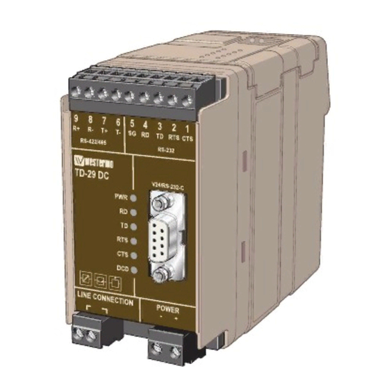
6.2 Connections RS-485 Interface LED indicators Line connection Power supply 6.3 LED Status Indicators LED on Power on LED off Power off LED on Transmit line data active LED off Transmit line data inactive LED on Receive line data active LED off Receive line data inactive LED on... -
Page 10: Rs-485 Interface
6.4 RS-485 Interface 9-position ITU-T V.11 Screw terminal Direrction Description Description In/Out A (T–) Transmitter/Receiver The definations R+/R–,T+T– can be varios between In/Out B (T+) Transmitter/Receiver different manufactures. 6.5 Line Interface 2-position Screw terminal Direction Description In/Out Transmitter/Receiver Transmitter/Receiver In/Out 6.6 Power Interface Connection Description... -
Page 11: Configuration
6.7 Configuration S2:1–4 S1:1–8 6.7.1 DIP switch settings DIP-switches is assessable under the lid on top of the unit. DIP-switches is used to configure the modem. Warning! Prevent damage to internal electronics from electrostatic discharges (ESD) by discharging your body to a grounding point (e.g. use of wrist strap), before the lid on top of the modem is removed. - Page 12 Switch block 1 – S1 Character format Selection of transmission level* 10 bits –9 dBm 1 2 3 4 5 6 7 8 1 2 3 4 5 6 7 8 11 bits 5 dBm 1 2 3 4 5 6 7 8 1 2 3 4 5 6 7 8 * Load 600 Ω...
-
Page 13: Functional Description
7. Functional description 7.1 Block diagram Screw terminal 1–5, 7–9 not used S2:4 S2:3 Amplifier S1:6 Line switch S1:4 Line Demodulator S1:7 Insulateted Power Supply Power Supply –5V 7.2 RS-485 connection 2-wire RS-485 equipment TD-29P Twisted pair Transmitter/ Transmitter/ A/A’ A/A’... -
Page 14: Line Connection
7.3 Line connection 2-position detachable screw terminal LINE CONNECTION POWER – LINE CONNECTION LINE CONNECTION LINE CONNECTION POWER POWER POWER – – – Multidrop half duplex with TD-29P Termination to be set with DIP-switches GB.28 6611-2021... - Page 15 OWN COMMENTS ................................................................................................................................................................................................................................................................................................................................................................................................................................................................................................................................................................................................................................................................6611-2021 GB.29...
- Page 16 Westermo Teleindustri AB • SE-640 40 Stora Sundby, Sweden Phone +46 16 42 80 00 Fax +46 16 42 80 01 E-mail: info@westermo.se Westermo Web site: www.westermo.com Subsidiaries Westermo Data Communications Ltd Westermo Data Communications S.A.R.L. Unit 14 Talisman Business Centre • Duncan Road 9 Chemin de Chilly 91160 CHAMPLAN Park Gate, Southampton •...
Need help?
Do you have a question about the TD-29 AC and is the answer not in the manual?
Questions and answers