Table of Contents
Advertisement
Quick Links
Advertisement
Table of Contents

Related Manuals for Westermo TD-23


Summary of Contents for Westermo TD-23
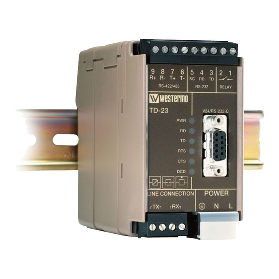
- Page 1 TD-23 Leased Line V.23 Modem Multidrop applications...
- Page 2 6600-2204...
-
Page 3: General Information
Under no circumstances shall Westermo be responsible for any loss of data or income or any special, incidental, and consequential or indirect damages howsoever caused. -
Page 4: Safety And Regulations
Safety and Regulations Warning signs are provided to prevent personal injury and/or damages to the product. The following levels are used: Level of warning Description Consequence Consequence personal injury material damage Indicates a potentially Possible death or Major damage to the hazardous situation major injury product... -
Page 5: Before Installation
Before installation: Read this manual completely and gather all information on the product. Make sure that you understand it fully. Check that your application does not exceed the safe operating specifications for this product. WARNING - SAFETY DURING INSTALLATION The product must be installed by qualified service personnel and built in to an apparatus cabinet or similar, where access is restricted to service personnel only. -
Page 6: Care Recommendations
If the product is used in a manner not according to specification, the protection provided by the equipment may be impaired. If the product is not working properly, contact the place of purchase, nearest Westermo distributor office or Westermo technical support. -
Page 7: Declaration Of Conformity
Declaration of Conformity Hereby, Westermo declares that this product is in compliance with applicable EU directives and UK legislations. The full declaration of conformity and other detailed information is available at www.westermo.com/support/product-support. Agency approvals and standards compliance Type Approval / Compliance... -
Page 8: Type Tests And Environmental Conditions
Type tests and environmental conditions Electromagnetic Compatibility Phenomena Test Description Test levels EN 61000-4-2 Enclosure contact ± 6 kV Enclosure air ± 8 kV RF field AM IEC 61000-4-3 Enclosure 6 V/m 80% AM (1 kHz) 2000 – 2700 MHz modulated 10 V/m 80% AM (1 kHz), 80 –... - Page 9 16 units over a distance of up to 25 km (15.5 miles). TD-23 is intended for mounting on a 35 mm DIN-rail, where the modem is attached and locked in a single action. … Data rate 1200 bit/s (V.23) …...
-
Page 10: Functional Description
Functional description Block diagram Modulated data Line relay 2 or 4-wire Selectable Selectable output level input sensitivity Modem Analog filter Frequency Frequency DIP-switches modulation demodulation Processor Modem Data Data chip buffer buffer control RTS CTS DCD RD TD TD RD Relay RS-232 RS-422/485... -
Page 11: Interface Specifications
Interface specifications Power Rated voltage 12 to 48 VDC 12 to 27 VAC Operating voltage 10 to 60 VDC 10 to 30 VAC Rated current 125 mA @ 12 VDC 50 mA @ 24 VDC 28 mA @ 48 VDC 125 mA @ 12 VAC 50 mA @ 24 VAC 25 mA @ 32 VAC Rated frequency DC / AC 48 –... - Page 12 RS-422/485 Electrical specification EIA RS-485 2-wire or 4-wire twisted pair Data rate 300 bit/s – 1200 bit/s Data format 7 or 8 data bits, Odd, even or none parity, 1 or 2 stop bits; Σ 9-12 bits Protocol Transparent Retiming Turn around time 4.2 ms (half duplex) Transmission range...
- Page 13 Relay (optional) Rated voltage Up to 48 VDC Operating voltage Up to 60 VDC Contact rating 50 mA @ 48 VDC 8 Ω Contact resistance Transmission range ≤ 3 m, depending on data rate and cable type Function The output follows the transmit carrier, I.e. output shorted when carrier is ON.
- Page 14 Location of interface ports, LEDs and DIP-switches RS-422/485 Product 9-pos. Direction* Description marking R+ (A’) Receive No 9 RS-422/485 4-wire R– (B’) Receive No 8 R– RS-422/485 4-wire T+ (A) Transmit RS-422/485 4-wire No 7 T+/R+ (A/A’) Transmit/Receive In/Out RS-422/485 2-wire T–...
- Page 15 LED Indicators Status Description In service Power Out of service Data transmitted on the RS-232 or RS-485 port Receive data No data transmitted on the RS-232 or RS-485 port Data received on the RS-232 or RS-485 port Transmit data No data received on the RS-232 or RS-485 port RTS signal active on the RS-232 port Request to send...
-
Page 16: Dip Switch Settings
DIP-switch settings Before DIP-switch settings: CAUTION - ELECTROSTATIC DISCHARGE (ESD) Prevent electrostatic discharge damages to internal electronic parts by discharging your body to a grounding point (e.g. use a wrist strap). NOTE - DIP-SWITCH ALTERATIONS DIP-switch alterations are only effective after a power on. S1 DIP-switch Selection of transmission level 3 dBm... - Page 17 Selection of minimum level, DCD detection specifies the minimum power level the receiver can handle. With the receiver having a dynamic range of 30 dBm, this means that with the level set to –15 dBm the TD-23 will pick up signals in the range –15 dBm to –45 dBm. We recommend that you try your network with the factory settings.
-
Page 18: S2 Dip-Switch
S2 DIP-switch Selection of 2/4 wire RS-422/485 side Deactivate 2-wire 4-wire RS-422/485 1 2 3 4 5 6 7 8 1 2 3 4 5 6 7 8 1 2 3 4 5 6 7 8 All RS-422/485 lines should be terminated at the end-points. The RS-422/485 interface also has a fail-sate circuit which forces a non-active line into idle state. -
Page 19: Factory Settings
S3 DIP-switch RS-422/485 termination No termination 2-wire termination with 4-wire termination with failsafe; or failsafe failsafe; T+/R+ and T– /R– R+ and R– 1 2 3 4 1 2 3 4 1 2 3 4 Factory settings 1 2 3 4 1 2 3 4 5 6 7 8 1 2 3 4 5 6 7 8 6600-2204... - Page 20 Slave unit Termination recommendations The RS-422/485 line must be terminated. In the TD-23 the termination is combined with fail-safe functionality. For that reason it is important that the termination is used not to get undefined states when the bus is in three state condition.
- Page 21 Mounting This unit should be mounted on 35 mm DIN-rail, which is horizontally mounted inside an apparatus cabinet, or similar. Snap on mounting, see figure. 10 mm * (0.4 inches) Cooling 25 mm This unit uses convection cooling. To avoid obstructing the airflow around the unit, use the following spacing rules. Minimum spacing 25 mm (1.0 inch) above /below and 10 mm (0.4 inches) left /right the unit. Spacing is recommended for...
-
Page 22: Application Examples
Application examples RS-232, 2-wire connection 2-wire twisted pair DIP-switch setting for both units 1 2 3 4 5 6 7 8 1 2 3 4 5 6 7 8 1 2 3 4 6600-2204... - Page 23 Multidrop application 1 2 3 4 5 6 7 8 RS-485 1 2 3 4 5 6 7 8 1 2 3 4 Master 1 2 3 4 5 6 7 8 1 2 3 4 5 6 7 8 1 2 3 4 5 6 7 8 1 2 3 4 5 6 7 8 1 2 3 4...
- Page 24 Westermo • Metallverksgatan 6, SE-721 30 Västerås, Sweden Tel +46 16 42 80 00 Fax +46 16 42 80 01 E-mail: info@westermo.com www.westermo.com REV. I 6600-2204 2021-11 Westermo Network Technologies AB, Sweden...
Need help?
Do you have a question about the TD-23 and is the answer not in the manual?
Questions and answers