
Related Manuals for Honeywell BendixKing KN 62A


Summary of Contents for Honeywell BendixKing KN 62A
- Page 1 INSTALLATION MANUAL KN 62/62A/64 DISTANCE MEASURING EQUIPMENT MANUAL NUMBER 006-00144-0007 REVISION 7 November, 2004...
- Page 2 ©1979, 2000, 2004 Honeywell International Inc. REPRODUCTION OF THIS PUBLICATION OR ANY PORTION THEREOF BY ANY MEANS WITHOUT THE EXPRESS WRITTEN PERMISSION OF HONEYWELL IS PROHIBITED, EXCEPT TO THE EXTENT REQUIRED FOR INSTALLATION OR MAINTENANCE OF THE RECIPIENT'S EQUIPMENT. FOR FURTHER INFORMATION CONTACT THE MANAGER, TECHNICAL PUBLICATIONS, HONEYWELL, ONE TECHNOLOGY CENTER, 23500 WEST 105TH STREET OLATHE KS 66061 TELEPHONE: (913) 782-0400.
- Page 3 BENDIX/KING KN 62/62A/64 REVISION HISTORY KN 62/62A/64 Installation Manual Part Number: 006-00144-0007 For each revision, Add, delete or replace pages as indicated. REVISION: 7, November, 2004 ITEM ACTION All pages Remove and Replace Rev 7, November/2004 00144I06.TDC Page R-1...
- Page 4 BENDIX/KING KN 62/62A/64 THIS PAGE RESERVED Rev 7, November/2004 00144I06.TDC Page R-2...
-
Page 5: Table Of Contents
BENDIX/KING KN 62/62A/64 SECTION I GENERAL INFORMATION INTRODUCTION..................1-1 EQUIPMENT DESCRIPTION ..............1-1 TECHNICAL CHARACTERISTIC ..............1-1 1.3.1 DME CHANNEL SOURCES ................1-3 1.3.2 UNIT RESONANT FREQUENCY ..............1-5 UNITS AND ACCESSORIES ...............1-5 1.4.1 KN 62 DME ....................1-5 1.4.2 KN62A......................1-5 1.4.3 KN 64 DME ....................1-5 1.4.4 KN 62/62A/64 INSTALLATION KIT ..............1-6 LICENSE REQUIREMENTS................1-6... - Page 6 BENDIX/KING KN 62/62A/64 LIST OF FIGURES FIGURE 1-1 KN 62/62A/64 CRITICAL FREQUENCIES........1-5 FIGURE 2-1 MOLEX TERMINALS AND TOOLS..........2-5 FIGURE 2-2 KN 62/62A/64 PIN FUNCTION .............2-8 FIGURE 2-3 ANTENNA CABLE ASSEMBLY.............2-11 FIGURE 2-4 KN 62/62A/64 INTERCONNECT ..........2-13 FIGURE 2-5 KN 62/62A/64 TO NARCO NAV 122 INTERCONNECT ....2-15 FIGURE 2-6 DUAL SLIP CODE CONTROL UNIT INTERCONNECT ....2-17 FIGURE 2-7...
- Page 7 BENDIX/KING KN 62/62A/64 LIST OF TABLES TABLE 1-1 SHIFTED BCD DME CHANNELING CODES .......1-3 TABLE 1-2 2X5 DME CHANNELING CODES..........1-4 TABLE 1-3 SLIP CODE DME CHANNELING CODES........1-4 TABLE 1-4 KN 62/62A/64 INSTALLATION KIT..........1-6 TABLE 2-1 KN 62/62A/64 PIN FUNCTION LIST..........2-9 Rev 7, November/2004 00144I06.TDC Page TOC-3...
-
Page 8: Rev 7, November/2004 00144I06.Tdc Page
BENDIX/KING KN 62/62A/64 Rev 7, November/2004 00144I06.TDC Page TOC-4... -
Page 9: General Information
BENDIX/KING KN 62/62A/64 SECTION I GENERAL INFORMATION INTRODUCTION This manual contains information relative to the physical, mechanical, and electrical characteris- tics and installation procedures for the KN 62/62A/64 DME. The KN 64 has lower output power than the KN 62/62A. The KN 64 is not TSO’ed. EQUIPMENT DESCRIPTION The KN 62/62A/64 is a panel mounted, 200 channel DME employing the latest state of the art sol- id-state transmitter and large scale integrated circuit (LSI) technology. - Page 10 BENDIX/KING KN 62/62A/64 SPECIFICATION CHARACTERISTIC D. Gas discharge display OUTPUT POWER: 50 watts peak, pulsed power minimum (35 watts, KN 64) 100 watts nominal (50 watts, KN 64) MAXIMUM DISPLAY RANGE:* 389 nautical miles PANEL HEIGHT: 1.3 inches (3.30 cm) maximum ACQUISITION SENSITIVITY: -82dBm minimum, -87dBm nominal (-78dBm minimum, -87dBm nominal, KN 64)
-
Page 11: Dme Channel Sources
BENDIX/KING KN 62/62A/64 POWER REQUIREMENTS: 11-33VDC at 15 watts 066-1068-04 AND 066-1088-01 ONLY BACKLIGHTING: NOMINAL 14VDC AT 2 WATTS NOMINAL 28VDC AT 2 WATTS CHANNELING SOURCES: a. Internal b. External control head providing shifted BCD code such as KFS 560B. c. -
Page 12: Table 1-2 2X5 Dme Channeling Codes
BENDIX/KING KN 62/62A/64 TABLE 1-2 2 x 5 DME CHANNELING CODES Frequen- cy Mhz 0 = Connected to Remote Control Common 1 = Open TABLE 1-3 SLIP CODE DME CHANNELING CODES Frequen- cy Mhz 0 = Connected to Remote Control Common 1 = Open Rev 7, November/2004 00144I06.TDC... -
Page 13: Unit Resonant Frequency
BENDIX/KING KN 62/62A/64 1.3.2 UNIT RESONANT FREQUENCIES The following critical frequencies are mechanical resonance of the unit under test that have peak acceleration amplitude greater than twice the input acceleration amplitude. There were no ob- served changes in performance of the unit under test. Figure 1-1 KN 62/62A/64 CRITICAL FREQUENCIES UNITS AND ACCESSORIES 1.4.1... -
Page 14: Kn 62/62A/64 Installation Kit
BENDIX/KING KN 62/62A/64 1.4.4 KN 62/62A/64 INSTALLATION KIT The KN 62/62A/64 installation kit, P/N 050-01611-XXXX is available in two versions. The -0000 and the -0001. The contents of the kit are listed below: TABLE 1-4 KN 62/62A/64 INSTALLATION KIT PART NUMBER DESCRIPTION -0000 -0001... -
Page 15: Installation
BENDIX/KING KN 62/62A/64 SECTION II INSTALLATION GENERAL INFORMATION This section contains information relative to the installation and wiring of the KN 62/62A/64 DME. A close adherence to methods and procedures discussed herein is required. 2.1.1 KN 62A ONLY The conditions and tests required for TSO approval of this article are minimum performance stan- dards. -
Page 16: Kn 62/62A/64 Installation
Recommendations on stack cooling are contained in Bendix/King Installation Bulletin #55 and #143 revised. Failure to provide stack cooling will certainly lead to increased avionics maintenance costs and may void the Honeywell warranty. 2.3.2 KN 62/62A/64 INSTALLATION (FIGURES THROUGH 2-18) Plan a location on the aircraft panel that is clearly visible and within easy access of the pilot. -
Page 17: Molex Connector Assembly
BENDIX/KING KN 62/62A/64 2.3.3 MOLEX CONNECTOR ASSEMBLY (FIGURE 2-1) Solderless Contact Terminal Assembly using Molex Crimper Refer to instructions in Section 2.3.3. Solderless Contact Terminal Assembly using Pliers Strip each wire 5/32” for contact terminal (P/N 030-01107-0030). (The last two digits of the contact terminal part number indicate the number of terminals furnished). - Page 18 BENDIX/KING KN 62/62A/64 antenna and six (6) feet from a transponder antenna. Where practical, plan the antenna location to keep cable lengths as short as possible, and avoid sharp bends in the cable to minimize the VSWR. To prevent RF interference, the antenna must be physically mounted a minimum distance of three feet from the KN 62/62A/64.
-
Page 19: Figure 2-1 Molex Terminals And Tools
BENDIX/KING KN 62/62A/64 FIGURE 2-1 MOLEX TERMINALS AND TOOLS (Sheet 1 of 3) Rev 7, November/2004 00144I06.TDC Page 2-5... - Page 20 BENDIX/KING KN 62/62A/64 FIGURE 2-1 MOLEX TERMINALS AND TOOLS (Sheet 2 of 3) Rev 7, November/2004 00144I06.TDC Page 2-6...
- Page 21 BENDIX/KING KN 62/62A/64 FIGURE 2-1 MOLEX TERMINALS AND TOOLS (Sheet 3 of 3) Rev 7, November/2004 00144I06.TDC Page 2-7...
-
Page 22: Figure 2-2 Kn 62/62A/64 Pin Function
BENDIX/KING KN 62/62A/64 FIGURE 2-2 KN 62/62A/64 PIN FUNCTION Rev 7, November/2004 00144I06.TDC Page 2-8... -
Page 23: Table 2-1 Kn 62/62A/64 Pin Function List
BENDIX/KING KN 62/62A/64 TABLE 2-1 KN 62/62A/64 PIN FUNCTION LIST --------------------- AUDIO LOW --------------------- AUDIO HI --------------------- DME COMMON --------------------- SLIP CODE SELECT --------------------- +14vdc LIGHT DIMMER --------------------- +28vdc LIGHT DIMMER SELECT <-- --------------------- K400/KE/K1 DME CHANNEL LINE --------------------- 2X5 CODE SELECT --------------------- 10 BIT FREQUENCY <--... - Page 24 BENDIX/KING KN 62/62A/64 Rev 7, November/2004 00144I06.TDC Page 2-10...
-
Page 25: Figure 2-3 Antenna Cable Assembly
BENDIX/KING KN 62/62A/64 FIGURE 2-3 ANTENNA CABLE ASSEMBLY (P/N 030-00101-0002, R-9) Rev 6, May/2004 00144I06.TDC Page 2-11... - Page 26 BENDIX/KING KN 62/62A/64 Rev 6, May/2004 00144I06.TDC Page 2-12...
-
Page 27: Figure 2-4 Kn 62/62A/64 Interconnect
BENDIX/KING KN 62/62A/64 FIGURE 2-4 KN 62/62A/64 INTERCONNECT (Dwg. No. 155-01296-0000, R-8) Rev 6, May/2004 00144I06.TDC Page 2-13... - Page 28 BENDIX/KING KN 62/62A/64 Rev 6, May/2004 00144I06.TDC Page 2-14...
- Page 29 BENDIX/KING KN 62/62A/64 FIGURE 2-5 KN 62A/64 TO NARCO NAV 122 INTERCONNECT (Dwg. No. 155-01339-0000, R-5) Rev 6, May/2004 00144I06.TDC Page 2-15...
- Page 30 BENDIX/KING KN 62/62A/64 Rev 6, May/2004 00144I06.TDC Page 2-16...
-
Page 31: Figure 2-6 Dual Slip Code Control Unit Interconnect
BENDIX/KING KN 62/62A/64 FIGURE 2-6 DUAL SLIP CODE CONTROL UNIT INTERCONNECT (Dwg. No. 155-01334-0000, R-5) Rev 6, May/2004 00144I06.TDC Page 2-17... - Page 32 BENDIX/KING KN 62/62A/64 Rev 6, May/2004 00144I06.TDC Page 2-18...
-
Page 33: Figure 2-7 Dual Bcd Control Unit Interconnect
BENDIX/KING KN 62/62A/64 FIGURE 2-7 DUAL BCD CONTROL UNIT INTERCONNECT (Dwg. No. 155-01335-0000, R-5) Rev 6, May/2004 00144I06.TDC Page 2-19... - Page 34 BENDIX/KING KN 62/62A/64 Rev 6, May/2004 00144I06.TDC Page 2-20...
-
Page 35: Figure 2-8 Dual 2X5 Control Unit Interconnect
BENDIX/KING KN 62/62A/64 FIGURE 2-8 DUAL 2 x 5 CONTROL UNIT INTERCONNECT (Dwg. No. 155-01336-0000, R-5) Rev 6, May/2004 00144I06.TDC Page 2-21... - Page 36 BENDIX/KING KN 62/62A/64 Rev 6, May/2004 00144I06.TDC Page 2-22...
-
Page 37: Figure 2-9 Slip Code And 2X5 Control Unit Interconnect
BENDIX/KING KN 62/62A/64 FIGURE 2-9 SLIP CODE AND 2 x 5 CONTROL UNIT INTERCONNECT (Dwg. No. 155-01333-0000, R-5) Rev 6, May/2004 00144I06.TDC Page 2-23... - Page 38 BENDIX/KING KN 62/62A/64 Rev 6, May/2004 00144I06.TDC Page 2-24...
-
Page 39: Figure 2-10 Slip Code And Bcd Control Unit Interconnect
BENDIX/KING KN 62/62A/64 FIGURE 2-10 SLIP CODE AND BCD CONTROL UNIT INTERCONNECT (Dwg. No. 155-01337-0000, R-5) Rev 6, May/2004 00144I06.TDC Page 2-25... - Page 40 BENDIX/KING KN 62/62A/64 Rev 6, May/2004 00144I06.TDC Page 2-26...
-
Page 41: Figure 2-11 2X5 And Bcd Control Unit Interconnect
BENDIX/KING KN 62/62A/64 FIGURE 2-11 2 x 5 AND BCD CONTROL UNIT INTERCONNECT (Dwg. No. 155-01338-0000, R-5) Rev 6, May/2004 00144I06.TDC Page 2-27... - Page 42 BENDIX/KING KN 62/62A/64 Rev 6, May/2004 00144I06.TDC Page 2-28...
-
Page 43: Figure 2-12 Nav 1 - Nav 2 Channeling Of A Kn 62/62A/64 From
BENDIX/KING KN 62/62A/64 FIGURE 2-12 NAV 1 - NAV 2 CHANNELING OF A KN 62/62A/64 FROM TWO KX 155/165’S (Dwg. No. 696-3423-00, R-0) Rev 6, May/2004 00144I06.TDC Page 2-29... - Page 44 BENDIX/KING KN 62/62A/64 Rev 6, May/2004 00144I06.TDC Page 2-30...
-
Page 45: Figure 2-13 Kn 62/62A/64 Outline And Mounting Drawing
BENDIX/KING KN 62/62A/64 FIGURE 2-13 KN 62/62A/64 OUTLINE AND MOUNTING DRAWING (Dwg. No. 155-05280-0000, R-AA) Rev 6, May/2004 00144I06.TDC Page 2-31... - Page 46 BENDIX/KING KN 62/62A/64 Rev 6, May/2004 00144I06.TDC Page 2-32...
-
Page 47: Figure 2-14 Kn 62/62A/64 Installation Drawing
BENDIX/KING KN 62/62A/64 FIGURE 2-14 KN 62/62A/64 INSTALLATION DRAWING (Dwg. No. 155-05281-0000, R-4) Rev 6, May/2004 00144I06.TDC Page 2-33... - Page 48 BENDIX/KING KN 62/62A/64 Rev 6, May/2004 00144I06.TDC Page 2-34...
-
Page 49: Figure 2-15 Kn 62/62A/64 Installation Drawing
BENDIX/KING KN 62/62A/64 FIGURE 2-15 KN 62/62A/64 INSTALLATION DRAWING (Dwg. No. 155-05281-0001, R-1) Rev 6, May/2004 00144I06.TDC Page 2-35... - Page 50 BENDIX/KING KN 62/62A/64 Rev 6, May/2004 00144I06.TDC Page 2-36...
- Page 51 BENDIX/KING KN 62/62A/64 FIGURE 2-16 KA 60 ANTENNA INSTALLATION DRAWING (Dwg. No. 155-05289-0000, R-AB) Rev 6, May/2004 00144I06.TDC Page 2-37...
- Page 52 BENDIX/KING KN 62/62A/64 Rev 6, May/2004 00144I06.TDC Page 2-38...
- Page 53 BENDIX/KING KN 62/62A/64 Figure 2-17 KA 61 Installation Drawing (Page 1 of 2) Rev 6, May/2004 00144I06.TDC Page 2-39...
- Page 54 BENDIX/KING KN 62/62A/64 Rev 6, May/2004 00144I06.TDC Page 2-40...
- Page 55 BENDIX/KING KN 62/62A/64 Figure 2-17 KA 61 Installation Drawing (Page 2 of 2) Rev 6, May/2004 00144I06.TDC Page 2-41...
- Page 56 BENDIX/KING KN 62/62A/64 Rev 6, May/2004 00144I06.TDC Page 2-42...
-
Page 57: Figure 2-18 030-00005-0000 Connector Assembly
BENDIX/KING KN 62/62A/64 FIGURE 2-18 030-00005-0000 CONNECTOR ASSEMBLY (Dwg. No. 155-05267-0000, R-0) Rev 6, May/2004 00144I06.TDC Page 2-43... - Page 58 BENDIX/KING KN 62/62A/64 Rev 6, May/2004 00144I06.TDC Page 2-44...
-
Page 59: Operation
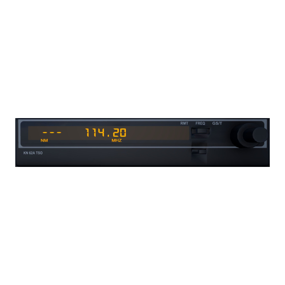
BENDIX/KING KN 62/62A/64 SECTION III OPERATION GENERAL It is recommended that power to the KN 62/62A/64 be turned on only after engine start-up, as this procedure increases the reliability of the solid state circuitry. The KN 62/62A/64 front panel controls consist of an ON-OFF switch, a function switch, and fre- quency selection knobs (Figure 3-1). -
Page 60: Figure 3-1 Kn 62/62A/64 Frequency Mode
BENDIX/KING KN 62/62A/64 When operating dual KN 62/62A/64’s, the respective DME’s will interfere with each other when the NAV frequencies differ by 5.3MHz (for example, 108.00MHz and 113.3MHz). This interfer- ence results in premature flags or loss of ”Lock-On”. Should this occur, one of the KN 62/62A/64’s should be either turned off or tuned to a different NAV frequency so that the 5.3MHz difference is eliminated. -
Page 61: Figure 3-3 Kn 62/62A/64 Remote Mode
BENDIX/KING KN 62/62A/64 FIGURE 3-3 KN 62/62A/64 remote mode Rev 6, May/2004 00144I06.TDC Page 3-3... - Page 62 BENDIX/KING KN 62/62A/64 Rev 6, May/2004 00144I06.TDC Page 3-4...
Need help?
Do you have a question about the BendixKing KN 62A and is the answer not in the manual?
Questions and answers