Table of Contents
Advertisement
Quick Links
This document contains technology under
Manual No. 10902-4
The export jurisdiction of the U.S. Department
March 19, 2004
Of Commerce, Export Administration Act of
1979, as amended, Title 50, U.S.C., App
2401 et seq and EAR 15 CFR 730
ECCN: 9E990
U.S. Schedule B: 4906-00-0000
8500C/8500C+ System
Maintenance Manual
Model 8500C/C+ Balancer/Analyzer System
Chadwick-Helmuth
A Business Unit of Honeywell International, Inc.
Advertisement
Chapters
Table of Contents
Troubleshooting

Related Manuals for Honeywell Chadwick-Helmuth 8500C


Summary of Contents for Honeywell Chadwick-Helmuth 8500C
- Page 1 Of Commerce, Export Administration Act of 1979, as amended, Title 50, U.S.C., App 2401 et seq and EAR 15 CFR 730 ECCN: 9E990 U.S. Schedule B: 4906-00-0000 8500C/8500C+ System Maintenance Manual Model 8500C/C+ Balancer/Analyzer System Chadwick-Helmuth A Business Unit of Honeywell International, Inc.
- Page 2 Chadwick-Helmuth. Chadwick-Helmuth 4601 N. Arden Drive El Monte, CA 91731 (626) 575-6161 Fax: (626) 350-4236 BBS: (626) 350-9697 E-mail: Chadwick@chadwick-helmuth.com Manual No. 10902-4 Chadwick-Helmuth A Business of Honeywell International, Inc.
- Page 3 Changes and Revisions Chadwick-Helmuth reserves the right to issue changes and revisions to this user guide on an as-needed basis. Safety Notices Throughout the user guide safety notices appear. The safety notices have the following headings and formats. NOTE: A suggestion on how to carry out a task. CAUTION Potential for damage to equipment.
- Page 4 The following table shows the record of revisions for this user guide: Revision Page/ Description Approval Date Number Paragraph Initial release February 17, 2003 A.4.4.3 Correct channel numbers for P-3 March 19, 2004 Harness, P/N 14440, Test Procedure Chadwick-Helmuth A Business Unit of Honeywell International, Inc.
-
Page 5: Table Of Contents
Contents List of Figures............ix List of Tables . - Page 6 5.7.4.1 Battery Pack Check ........5-49 Chadwick-Helmuth A Business Unit of Honeywell International, Inc.
- Page 7 Contents 5.7.4.2 Battery Pack Replacement (Figure 5-17)..... . . 5-49 5.7.5 Fuse Replacement ..........5-50 5.7.5.1 8520C Power Supply Board (A2) Fuse (Figure 5-20) .
- Page 8 Index ............. I-1 viii Chadwick-Helmuth A Business Unit of Honeywell International, Inc.
-
Page 9: List Of Figures
List of Figures Figure 1-1. 8500C/C+ Balance/Analyzer ........1-3 Figure 1-2. - Page 10 Figure D-12. Wiring Diagram 8520CS ........D-21 Chadwick-Helmuth A Business Unit of Honeywell International, Inc.
- Page 11 List of Tables Table 1-1. 8500C/C+ Balancer/Analyzer System, Major Components ... . . 1-7 Table 1-2. System Interconnect Cables........1-8 1 .
- Page 12 List of Tables Chadwick-Helmuth A Business Unit of Honeywell International, Inc.
-
Page 13: Chapter 1. Introduction
1.1 About This Manual 1.1.1 Purpose and Function This manual contains maintenance instructions at the field replaceable component level for the Chadwick-Helmuth 8500C/C+ Balancer/Analyzer Systems. Operating instructions are provided only to the extent needed to test the system. 1.2 System Purpose And Function The 8500C/C+ Balancer/Analyzer system is used for both balance/track operations as well as vibration analysis. -
Page 14: System Physical Description
The disk drive is used to upload to the balancer/analyzer software (“charts”) for the specific aircraft tests, and to download acquired data. The vibration data balance solutions are printed on 4-3/8 inch wide thermal paper. Chadwick-Helmuth A Business Unit of Honeywell International, Inc. -
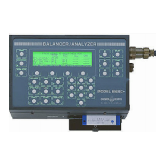
Page 15: Figure 1-1. 8500C/C+ Balance/Analyzer
System Physical Description The 8500C/C+ printer/disk drive assembly is composed of the following items: • Printer assembly: prints data and solutions on paper. • Printer board: interfaces with the printer. • Disk drive assembly: uploads software from the diskette to the balancer/analyzer assembly. •... -
Page 16: Figure 1-2. 8520C Signal Selector
Chapter 1 - Introduction Figure 1-2. 8520C Signal Selector Chadwick-Helmuth A Business Unit of Honeywell International, Inc. -
Page 17: Figure 1-3. System Cables
System Physical Description Figure 1-3. System Cables 8500C/8500C+ System Maintenance Manual... -
Page 18: Figure 1-4. System Accessories (Not To Scale)
Chapter 1 - Introduction Figure 1-4. System Accessories (not to scale) Chadwick-Helmuth A Business Unit of Honeywell International, Inc. -
Page 19: 8520C Signal Selector (Figure 1-2)
Leading Particulars 1.3.2 8520C Signal Selector (Figure 1-2) The 8520C signal selector switches to the appropriate Velocimeter and magnetic pickup or photocell channel as selected by the 8500C/C+, and sends those vibration signals to the 8500C/C+ for processing. The 8520C also routes 28 VDC power to the 8500C/C+. The front panel contains 12 connectors for connection to Velocimeter sources, and four connectors for connection to magnetic pickup, photocell, and optical tracker sources. -
Page 20: Table 1-2. System Interconnect Cables
11800 FasTrak Day-Night optical tracker, used in place of Strobex. Communicates with 8500C/C+ Smart Chart software. 10200 Optical Probe Provides optical inputs to photocell processor 10170. Chadwick-Helmuth A Business Unit of Honeywell International, Inc. - Page 21 Related Publications Table 1-3. Basic System Accessories (Continued) Part No. Nomenclature Purpose Qty. 11245 Gram Scale Pocket, Measures rotor balance weights. 120V 3030 Magnetic Pickup Provides magnetic pickup signals to 8500C/C+ via 8520C, or cable 8998 7310 Velocimeter Provides Velocimeter inputs to 8520C via cable 11210-50/11210-20 610-199 Printer paper...
-
Page 22: Table 1-4. Leading Particulars
200 to 600,000 rpm in arbitrary, user-selected steps FFT frequency resolution 461 lines up to 7.5 kHz, 400 lines up to 10 kHz FFT time domain weighting Kaiser window Frequency accuracy 0.22%, Fmax = 0.1% 1-10 Chadwick-Helmuth A Business Unit of Honeywell International, Inc. - Page 23 Related Publications Table 1-4. Leading Particulars (Continued) 8500C/C+ Balancer/Analyzer Parameter Characteristic Speed 1 spectrum per 3 seconds with 30,000 rpm range (varies with Fmax). Averaging (in balance mode only) 8 most recent balance measurements averaged excluding measurement outside one average deviation Phase accuracy +2.0 degrees (electrical)
-
Page 24: Table 1-5. Related Publications
Operation and Maintenance Instructions with Illustrated Parts Breakdown, Strobex Model 135M- 10473-1 Operation and Maintenance Manual for Photocell System PN 10252 11211 Model 8500C/C+ Quick Reference Guide III Specific Helicopter User’s Guide 1-12 Chadwick-Helmuth A Business Unit of Honeywell International, Inc. -
Page 25: Chapter 2. 8500C/C+ Handling And Installation
Chapter 2 8500C/C+ Handling And Installation Section 2.1 Preparation For Use..................2-1 Section 2.2 Repacking......................2-4 Section 2.3 Storage ......................2-4 2.1 Preparation For Use 2.1.1 Unpacking Open shipping container and remove carrying case and accessories. Open carrying case and remove major components, cables, and accessories. Check contents of shipping container and carrying case against enclosed Packing List. -
Page 26: Disk Installation (Figure 2-1)
2.1.5 Printer Paper Loading (Figure 2-3) Trim any ragged edges on paper roll. Tightly rewind roll and place in holder. Feed paper into printer using advance gear as shown (or paper advance button if power is applied). Chadwick-Helmuth A Business Unit of Honeywell International, Inc. -
Page 27: Figure 2-2. Removing Printer Paper
Preparation For Use NOTE: If paper is not feeding in straight, hold a finger against an edge to guide it into place as it feeds; otherwise, wait until paper is coming out of unit and then pull it into position. Ensure paper has no rumpled edges feeding into paper path. -
Page 28: Repacking
The components can withstand a temperature range of -40°C to +71°C and a relative humidity of up to 90% for extended periods. Store components in a cool, dry area. Shelf life is 10 years. Chadwick-Helmuth A Business Unit of Honeywell International, Inc. -
Page 29: Chapter 3. 8500C/C+ Operation
Chapter 3 8500C/C+ Operation Section 3.1 Softkey Functions (Figure 3-1) .................3-1 Section 3.2 8500C/C+ Warm-Start Procedure ..............3-1 Section 3.3 8500C/C+ Cold-Start Procedure ..............3-1 3.1 Softkey Functions (Figure 3-1) For maintenance purposes it helps to know what soft keys are and how they are manipulated. Although not required to perform the procedures in this manual, more detailed information on operating the 8500C/C+ balancer/analyzer can be found in Model 8500C Operator’s Manual (#9449-6), 8500C Quick Reference Guide III (#11211), or the 8500C/C+ User’s Guide for your aircraft. -
Page 30: Figure 3-1. 8500C Controls And Indicators
C A L I F O R N I A > SOFT KEYS SHOWS/HIDES SOFT KEY LABELS ASTERISK INDICATES MORE LABELS ARE AVAILABLE WHEN "MORE KEYS" IS PRESSED FILE: SOFTKEY3.DRW Figure 3-1. 8500C Controls and Indicators Chadwick-Helmuth A Business Unito of Honeywell International, Inc. -
Page 31: Figure 4-1. 8500C/C+ Balancer/Analyzer System Block Diagram
Chapter 4 System Theory of Operation Section 4.1 System Description....................4-1 Section 4.2 Detailed Description..................4-2 4.1 System Description A system block diagram is shown in Figure 4-1. The balancer/analyzer assembly acquires, displays, processes, and analyzes vibration data for fault analysis and balance correction. The printer/disk drive assembly loads, stores, and prints vibration and related data. -
Page 32: Chapter 4. System Theory Of Operation
2:1 multiplexer. The firmware automatically selects the low-frequency section for analysis of signals below 500 Hz. The high-frequency section is chosen for analysis above 500 Hz. Chadwick-Helmuth A Business Unit of Honeywell International, Inc. - Page 33 Detailed Description Both of the initial sections are implemented with precision resistors, capacitors, and a high-quality operational amplifier. This stage provides two functions. Its Q and corner frequency are set so that it contributes to the overall ten-pole low-pass response. Its corner frequency is low enough such that it also functions as an anti-alias filter for the following sampled data filter section.
-
Page 34: Figure 4-2. Analog Board Block Diagram
FILTER DETECTOR (2 ND STAGE) ANTI-ALIAS LOW-PASS FILTER (3 RD STAGE) TRACK HOLD SYSTEM DATA BUS ANALOG- TO MEMORY TO-DIGITAL ON DIGITAL CONVERTER BOARD FILE: FIG4-2.DRW Figure 4-2. Analog Board Block Diagram Chadwick-Helmuth A Business Unit of Honeywell International, Inc. - Page 35 Detailed Description 4.2.1.1.2 Digital Board (Figure 4-3) The digital board receives digital signals from the ADC on the analog board and digital serial communications from the microcontroller on the controller board in the Signal Selector 8520C. The signals from the analog board are analyzed and processed by the digital board, and the results are displayed on the liquid crystal display (LCD) or printed out by the printer.
- Page 36 LCD via the system data bus. The LCD resides in the 8500C/C+ behind a tough plastic window which protects it from damage without degrading readability. A resistive heater and EL lamp are integrated into the display. Chadwick-Helmuth A Business Unit of Honeywell International, Inc.
-
Page 37: Figure 4-3. Digital Board Block Diagram
Detailed Description CONTROL MAGNETIC COMMANDS PICKUP TIMING PULSE TO ANALOG SIGNAL CONTROLLER DETECTOR BOARD INPUT FROM 8520C TO/FROM PRINTER BOARD SERIAL COMMUNICATIONS COMMUNICATIONS CONTROLLER TO/FROM 8520C TO/FROM DISK DRIVE REALTIME KEYPANEL CLOCK VELOCIMETER 68008 DIGITAL SIGNAL MICRO- LOW-PASS FROM ANALOG PROCESSOR FILTERS BOARD... -
Page 38: Figure 4-4. Heater/El Control Board
+65°C. This protects the EL lamps whose life span is decreased when operated at high temperature. It also prevents the display heater from operating at high temperatures, in the event of a controller failure. Chadwick-Helmuth A Business Unit of Honeywell International, Inc. -
Page 39: Printer/Disk Drive Assembly
Detailed Description Display Heater. The filtered +27 VDC power from the power supply filter is regulated at +12 VDC and applied to the heater controller module. This module samples the resistance of the heater every 10 seconds. If the resistance falls below approximately 83 ohms, indicating that the screen temperature is below approximately 7°C, then the controller begins heating the display. -
Page 40: 8520C Signal Selector
4.2.2.1 Controller Board (Figure 4-6) The controller board routes analog inputs from the Velocimeters and magnetic or photocell pickups for processing by the 8500C/C+. The inputs are selected by the 8500C/C+. 4-10 Chadwick-Helmuth A Business Unit of Honeywell International, Inc. -
Page 41: Figure 4-6. Controller Board And Quad Peak Detector Board Block Diagram
Detailed Description Velocimeter Inputs. Twelve discrete Velocimeter connectors are mounted on the front panel of the 8520C. All inputs may be simultaneously connected to twelve transducers (Velocimeters). Each connector provides regulated +12 and -12 VDC power to a connected Velocimeter. Azimuth Pickup Inputs. -
Page 42: Velocimeter Bit (Figure 4-6)
The output of the bridge is applied across a FET switch and transformer. The transformer outputs are rectified and filtered to produce +5 VDC, one +12 VDC, and one -12 VDC output voltage. 4-12 Chadwick-Helmuth A Business Unit of Honeywell International, Inc. -
Page 43: Quad Peak Detector Board
Detailed Description The power supply contains a closed-loop regulator, which keeps the output voltages constant for varying input voltage and load. An optoisolator feeds back the output voltage across the isolation barrier. A light emitting diode (LED) indicates when power in on. OPTO-ISOLATOR/ REGULATOR/ DIODE... - Page 44 Chapter 4 - System Theory of Operation 4-14 Chadwick-Helmuth A Business Unit of Honeywell International, Inc.
-
Page 45: Table 5-1. Test Equipment
Chapter 5 Maintenance And Repair Section 5.1 Test Equipment....................5-1 Section 5.2 Routine Maintenance Procedures ..............5-3 Section 5.3 Periodic Inspection Procedures ................5-3 Section 5.4 Functional Tests ....................5-3 Section 5.5 Calibration Tests ....................5-12 Section 5.6 Troubleshooting Guide..................5-30 Section 5.7 Repair........................5-44 Section 5.8 Disassembly ......................5-51 Section 5.9 Reassembly......................5-69 Section 5.10 List of Field-Replaceable Components ............5-72 Section 5.11 Cage Codes .....................5-77... -
Page 46: Chapter 5. Maintenance And Repair
C-H #402-0841B (soldered pins) MS3116F8-4P (soldered pins) MS3126F8-4P (crimped pins) ITT Cannon #KPSE06F8-4P (crimped pins) ITT Cannon #KPT06F8-4P (soldered pins) RG-58 Coax Cable SHIELD FILENAME: TESTCABL.DRW Figure 5-1. Test Cable Fabrication Information Chadwick-Helmuth A Business Unit of Honeywell International, Inc. -
Page 47: Routine Maintenance Procedures
Routine Maintenance Procedures 5.2 Routine Maintenance Procedures Table 5-2 lists the procedures that should be done every 12 months to keep the 8500C/C+ system in good working order. Table 5-2. Routine Maintenance Procedures. Item Procedure 8500C/C+ Disk Drive Section 5.7.1.2 “Disk Drive Cleaning Procedure 8500C/C+ and 8520C Section 5.4 “Functional Tests”... -
Page 48: Power-Up Self-Test
Attention, users outside U.S.: The 11A Calibrator can also be calibrated under 50 Hz light. For 1714 rpm and 923 rpm cam rates, inner two rings on rotor disk are used. Remember to enter half these rates in 8500C/C+ setup screen, when called for in the following steps. Chadwick-Helmuth A Business Unit of Honeywell International, Inc. -
Page 49: Figure 5-3. Typical Balance Test Displays For 900 Rpm
Functional Tests NOTE: To undo mistaken entries, press the RESTORE soft key. On same line, press right arrow key twice to select last number (called “times factor”) with arrow keys. Key in 2 as new times factor. This entry now reads: x 2. Select BALANCE TYPE field with arrow keys. -
Page 50: Figure 5-4. Typical Balance Test Displays For 1800 Rpm
1800 +2 RPM 0.8 +0.08 IPS 275° +10° Press STOP key. Press SETUP key. Select INPUT field with arrow keys. Key in <2> with numeric key. Press ENTER soft key. Wait 10 seconds. Chadwick-Helmuth A Business Unit of Honeywell International, Inc. - Page 51 Functional Tests Press START key. Verify that display indicates (example in Figure 5-4): 1800 +2 RPM 0.8 +0.08 IPS 275° +10° Press STOP key. Set CAM RATE (RPM) switch on Calibrator 11A to 900. Press SETUP key on 8500C/C+. Key in 450 in BALANCE FREQUENCY field. Key in x2 as times factor.
-
Page 52: Spectrum Test
Key in 5000 with numeric keys in MAXIMUM FREQUENCY field. Press ENTER soft key. Wait 10 seconds. Press START key. Verify that spectrum is displayed (examples in Figure 5-5). 900 RPM CAM RATE Chadwick-Helmuth A Business Unit of Honeywell International, Inc. -
Page 53: Track Test
Functional Tests 1800 RPM CAM RATE Figure 5-5. Typical Spectrum Test Displays. Use left or right arrow keys to move cursor (dotted line) to 900 RPM. Verify that readout at top of display shows peak signal is 0.4 +0.04 IPS at 900 +5 RPM. Switch Calibrator to 1800 RPM CAM RATE. -
Page 54: Fastrak
923 rpm cam rates, inner two rings on rotor disk are used. Remember to enter half these rates in 8500C/C+ setup screen, when called for in the following steps. 5-10 Chadwick-Helmuth A Business Unit of Honeywell International, Inc. -
Page 55: Figure 5-6. Functional Test Setup (With Tracker)
Functional Tests 8500C BALANCER/ANALYZER BALANCER/ANALYZER PRINT START POWER SUPPLY 9100A SHOW/HIDE STOP MORE/KEYS BALANCE HELP STATUS SPECTRUM LOAD SETUP M O D E L 8 5 0 0 C < CHADWICK HELMUTH TRACK STORE ANNOTATE E L M O N T E , C A L I F O R N I A >... -
Page 56: Disk Drive Test Procedure
NOTE: These tests build successively on the first test in this section. Any settings not mentioned must be left as they were in the previous test. 5.5.1.1 Test Setup Connect equipment as shown in Figure 5-8. 5-12 Chadwick-Helmuth A Business Unit of Honeywell International, Inc. -
Page 57: Power-Up Self-Test
Calibration Tests 5.5.1.2 Power-Up Self-Test Hold down START key on 8500C/C+ and turn on power supply. NOTE: This erases all memory in 8500C/C+. Wait until Power-Up Self-Test display appears and release START key. 5.5.1.3 Amplitude, Frequency, and Phase Accuracy Tests This test uses a signal generator to input a signal with an exact amplitude, frequency, and phase relationship to the 8500C/C+. -
Page 58: Figure 5-8. 8500C/C+ Calibration Test Setup
Select <RPM> on display by pressing right arrow key once. Press CHANGE soft key to select <Hz>. Select <AUTO STOP> field with arrow keys. Press CHANGE soft key to select <MAN STOP>. Select PHASE UNITS field with arrow keys. 5-14 Chadwick-Helmuth A Business Unit of Honeywell International, Inc. -
Page 59: Noise And Spurious Signals Test
Calibration Tests Press CHANGE soft key to select <DEGREES>. Press ENTER soft key. Monitor signal generator output with spectrum analyzer with marker at 100 Hz. Adjust signal generator output channel connected to Velocimeter input until amplitude is 13.44 +/ - 0.05 mV RMS. Wait 10 seconds for 8500C/C+ gain to settle. - Page 60 Adjust signal generator output channel connected to Velocimeter input until amplitude is 13.44 +/- 0.05 mV RMS. Press SETUP key. Key in 10000 (Hz) with numeric keys in MAXIMUM FREQUENCY field. Press ENTER key. Wait 10 seconds. 5-16 Chadwick-Helmuth A Business Unit of Honeywell International, Inc.
-
Page 61: 8520C Signal Selector Test Procedure
Calibration Tests Press START key. Verify that no signal aliasing remains on display above 0.005 IPS. 5.5.2 8520C Signal Selector Test Procedure NOTE: These tests build successively on the first test in this section. Any settings not mentioned must be left as they were in the previous test. 5.5.2.1 Test Setup Connect equipment as shown in Figure 5-9. - Page 62 VIB LEVEL: 1.000 +0.04/-0.05 IPS PHASE ANGLE: 180° +/- 3° Press STOP key. Move cable 8278 to next Velocimeter channel position listed in Table 5-4 and move cable 10502 to next magnetic pickup cable position. 5-18 Chadwick-Helmuth A Business Unit of Honeywell International, Inc.
-
Page 63: Table 5-4. 8520C Velocimeter And Magnetic Pickup Amplitude, Frequency, And Phase
Calibration Tests Table 5-4. 8520C Velocimeter and Magnetic Pickup Amplitude, Frequency, and Phase Accuracy Channel Combinations Velocimeter Magnetic Pickup Channel Channel (Cable 8278) (Cable 10502) Press SETUP key. Select INPUT field with arrow keys. Key in Velocimeter channel number with numeric keys. Select PICKUP field with arrow keys. -
Page 64: Channel Crosstalk Test
Press SPECTRUM key on 8500C/C+. Press SETUP key. Key in 1000 <Hz> with numeric keys. Select SEEK field with arrow keys. Press CHANGE soft key to select <SEEK OFF>. Select INPUT field with arrow keys. 5-20 Chadwick-Helmuth A Business Unit of Honeywell International, Inc. -
Page 65: 8500C/C+ Spectrum Accuracy Test (With 8520C)
Calibration Tests Key in channel number with numeric keys (for example, 2 for first channel 1 test). Press ENTER soft key. Wait 10 seconds. Press START key. Verify that no noise signal is present on display above 0.01 IPS. Repeat steps c through l for remaining channel combinations listed in Table 5-5. For example, after channels 2 through 12 have been tested while cable 8278 was connected to channel 1, move cable 8278 to channel 2 and repeat test. - Page 66 2 next amplitudes to the left of the peak, and the 2 next amplitudes to the right. This process is described in the following steps. 5-22 Chadwick-Helmuth A Business Unit of Honeywell International, Inc.
-
Page 67: Figure 5-10. Spectrum Accuracy Test Setup
Calibration Tests P O W E R S U P P L Y 9 1 0 0 A C A B L E 1 0 8 1 3 C A B L E 1 0 8 1 1 8 5 0 0 C B A L A N C E R / A N A L Y Z E R B A L A N C E R / A N A L Y Z E R P R I N T S T A R T... - Page 68 + ( a m p . E ) The true amplitude of each harmonic peak should fall between the minimum and maximum values listed inTable 5-6; if any are out range, refer to Section 5.6, “Troubleshooting Guide.” 5-24 Chadwick-Helmuth A Business Unit of Honeywell International, Inc.
-
Page 69: Test Procedure: Low Frequency Range
Calibration Tests NOTE: These frequencies are based on a 580.0 Hz, square wave input. 8500C/C+ Firmware Version: ___________ 8500C/C+ Serial Number: ___________ Date:________ Table 5-6. Spectrum Accuracy, High Frequency Range True Amp. 2nd Amp. to 1st Amp. to Harmonic 1st Amp. to 2nd Amp. - Page 70 Press ENTER soft key. Wait 10 seconds and then press START key. The acquired spectrum shows a range of odd harmonic peaks on the 8500C/C+ display, from the 1st (fundamental) on. 5-26 Chadwick-Helmuth A Business Unit of Honeywell International, Inc.
- Page 71 Calibration Tests Use 8500C/C+ arrow keys to move cursor (dotted line) to fundamental peak. The amplitude readout (in IPS) is shown at the top of the display. Write down this measurement in Table 5-8. Repeat Steps s and t at the following signal generator frequency: 406.0 +/- 0.1 Hz, 308.0 +/- 0.1 Hz, 210.0 +/- 0.1 Hz, 154.0 +/- 0.1 Hz, 98.0 +/- 0.1 Hz.
-
Page 72: Table 5-7. Specification: Spectrum Accuracy, Low Frequency Range
______ IPS 51.0 Hz (3060 rpm) ______ IPS 21.0 Hz (1260 rpm) ______ IPS 9.0 Hz (540 rpm) ______ IPS 6.0 Hz (360 rpm) ______ IPS 3.0 Hz (180 rpm) ______ IPS 5-28 Chadwick-Helmuth A Business Unit of Honeywell International, Inc. -
Page 73: Figure 5-11. Troubleshooting Only: Spectrum Accuracy Test Setup W/O 8520C
Calibration Tests P O W E R S U P P L Y 9 1 0 0 A C A B L E 8 9 9 8 M A G P I C K U P I N P U T U N U S E D V E L O C I M E T E R I N P U T ( 6 P I N ) -
Page 74: Troubleshooting Guide
Observe static discharge precautions. The circuit boards in this equipment contain electrostatic-sensitive devices. Do not use magnetic tools when servicing the equipment and avoid touching the microcircuits on the circuit boards. 5-30 Chadwick-Helmuth A Business Unit of Honeywell International, Inc. -
Page 75: Table 5-8. Troubleshooting Guide
Troubleshooting Guide Table 5-8. Troubleshooting Guide 8500C/C+ Balancer/Analyzer Problem Solution “EXCEPTION ERROR” NOTE: If the exception error is caused by pressing the PRINT key, NOTE: This type of error can also be skip ahead to the troubleshooting caused by a problem with software procedure for this situation. - Page 76 (Figure 5-19, Sheet 2, J4/ P4) from digital board (Figure 5-17, A1). If error message has not reappeared upon power-up, replace keypad panel (Figure 5-17, (1)). 5-32 Chadwick-Helmuth A Business Unit of Honeywell International, Inc.
- Page 77 Troubleshooting Guide Table 5-8. Troubleshooting Guide 8500C/C+ Balancer/Analyzer Problem Solution “ANALOG FILTER FAILURE” (cont’d) NOTE: Intermittent failures are not likely to be caused by the keypad panel 6. Analog board is most likely at fault. Replace analog board (Figure 5-17, A2). “DISK INCORRECTLY FORMATTED”...
- Page 78 3. Measure resistance across P3 connector which connects to Heater/EL board. Resistance must be less than 100 Ω: if it is not, replace graphics module (Figure 5-17, (24)). 5-34 Chadwick-Helmuth A Business Unit of Honeywell International, Inc.
- Page 79 Troubleshooting Guide Table 5-8. Troubleshooting Guide 8500C/C+ Balancer/Analyzer Problem Solution 8500C/C+ LCD does not operate in cold 4. Heater/EL board is most likely at fault. temperature. (cont’d.) Replace Heater/EL board A4. 5. Graphics module is next most likely at fault Replace graphics module (Figure 5-17 (24)).
- Page 80 (Figure 5-19) for shorted or open connections which can be caused by loose or pinched wires, unplugged connectors, or worn-through insulation. 7. Printer assembly is most likely at fault. Replace printer assembly (Figure 5-18 (13)). 5-36 Chadwick-Helmuth A Business Unit of Honeywell International, Inc.
-
Page 81: Table 5-9. 8500C/C+ Balancer/Analyzer Functional Tests
Troubleshooting Guide Table 5-9. 8500C/C+ Balancer/Analyzer Functional Tests Problem Solution 5.4.1.3 Balance Test Readings do not meet specifications. 1. Ensure gap between magnetic pickup and screw is .030 +.010 in. 2. Perform 5.5.1.3, “Amplitude, Frequency, and Phase Accuracy Tests,” to determine whether fault is with 8500C/C+. - Page 82 4. Disk drive most likely at fault. Replace disk drive (Figure 5-18, 10). 5. Digital board next most likely at fault. Replace digital board (Figure 5-17, A1). 5-38 Chadwick-Helmuth A Business Unit of Honeywell International, Inc.
-
Page 83: Table 5-10. 8500C/C+ Balancer/Analyzer Calibration Tests
Troubleshooting Guide Table 5-10. 8500C/C+ Balancer/Analyzer Calibration Tests Problem Solution 5.5.1.3 Amplitude, Frequency, and Phase Accuracy Tests Vibration level does not meet specifications. 1. Check 8500C/C+ harness assembly (Figure 5-19) for shorted or open connectors which can be caused by loose or pinched wires, unplugged connectors, or worn-through insulation. - Page 84 (Figure 5-19) for shorted or open connections which can be caused by loose or pinched wires, unplugged connectors, or worn-through insulation. 4. Analog board is most likely at fault. Replace analog board (Figure 5-17, A2). 5-40 Chadwick-Helmuth A Business Unit of Honeywell International, Inc.
-
Page 85: Table 5-11. 8520C Signal Selector Tests
Troubleshooting Guide Table 5-11. 8520C Signal Selector Tests Problem Solution 5.5.2.3 amplitude, Frequency, and Phase Accuracy Test Vibration level, frequency reading, or phase 1. Check 8520C harness assembly angle does not meet specifications. (Figure 5-19) for shorted or open connections which can be caused by loose or pinched wires, unplugged connectors, or worn-through insulation. -
Page 86: Figure 5-12. Troubleshooting Flowchart: 8500 Pilot Light
PILOT LIGHT ON? ASSY. REMOVE POWER CONNECTOR FROM DISK DRIVE REPLACE DISK PILOT LIGHT ON? DRIVE RETURN 8500C TO FACTORY FOR REPAIR FILENAME: FLOWCHTA.DRW Figure 5-12. Troubleshooting Flowchart: 8500 Pilot Light 5-42 Chadwick-Helmuth A Business Unit of Honeywell International, Inc. -
Page 87: Figure 5-13. Troubleshooting Flowchart: 8520C Power Light
Troubleshooting Guide 8520C POWER LIGHT NOT ON: DISCONNECT J1 NOTE: THIS FLOWCHART ASSUMES THAT THE FUSE AND FROM CONTROLLER BOARD A1 HARNESS ASSEMBLIES HAVE ALREADY BEEN CHECKED. REPLACE P/S POWER LIGHT ON? BOARD A2 RECONNECT A1 & DISCONNECT QUAD PEAK DET. BOARD A3 FROM CONTROLLER BOARD A1... -
Page 88: Repair
Wipe surfaces with a clean, lint-free cloth moistened with a solution of water and a mild detergent. CAUTION Do not use solvents on the 8500C/C+ display window. Wipe surfaces with a clean, lint-free cloth moistened with clean water to remove detergent residue. 5-44 Chadwick-Helmuth A Business Unit of Honeywell International, Inc. -
Page 89: Disk Drive Cleaning Procedure
Repair Dry surfaces with a clean, dry, lint-free cloth, or allow to air dry. 5.7.1.2 Disk Drive Cleaning Procedure Disk drive heads can become dirty from extended use; symptoms usually include an increased number of disk read and write errors. Commercially available 3.5-inch disk drive cleaning kits provide special disks that are specifically designed to clean dirty heads. -
Page 90: Figure 5-14. Cable Schematics
POWER/SIGNAL +V 12-15 VDC INPUTS MAG/PHOTOCELL +28 VDC SIGNAL BRAID VELOCIMETER SIGNAL BRAID P5-1 FROM DIGITAL BOARD P5-3 FROM DIGITAL BOARD 8998 INPUT ADAPTER CABLE FILE: CABLES.DRW Figure 5-14. Cable Schematics 5-46 Chadwick-Helmuth A Business Unit of Honeywell International, Inc. -
Page 91: Inspection
Repair Hold disk with arrow facing up and pointing in and insert disk in 8500C/C+ disk drive- push in until drive button pops out (Figure 2-1). Press STATUS. Press FORMAT DSK soft key. Press FORMAT soft key. Because the cleaning disk contains no magnetic media, the message, DISK IS NOT CORRECTLY FORMATTED! will appear. -
Page 92: Eprom Change Procedure (Figure 5-15)
NOTE: NOTCHED ENDS ON EPROMS MUST BE IN DIRECTION SHOWN. LEFT ENDS OF EPROMS U8 & U9 MUST BE ALIGNED WITH U10. U8 & U9 MAY DIFFER IN SIZE. Figure 5-15. EPROM Locations on Digital Board 5-48 Chadwick-Helmuth A Business Unit of Honeywell International, Inc. -
Page 93: Battery Pack Check And Replacement
Repair Remove both EPROM’s as follows: using a small, straight-blade screwdriver, carefully pry up one end of EPROM just a little bit. Pry up other end a little. Go back and forth until EPROM is loose. CAUTION Trying to pry out the EPROM in one step will bend the EPROM pins. Remove new EPROM’s from container. -
Page 94: Fuse Replacement
Close unit while watching for pinched connector wires. Install bezel (4) on keypad panel (1), and secure with ten 4-40 x 3/16 php. blk. screws (32) and four 4-40 x 1/4 pan. blk. screws (33). 5-50 Chadwick-Helmuth A Business Unit of Honeywell International, Inc. -
Page 95: Disassembly
Disassembly 5.8 Disassembly Table 5-14. Tools for Disassembly/Reassembly #1 Phillips Head Screwdrive 1/4” Hex Driver 5.8.1 8500C/C+ Disassembly NOTE: Harness dressing and routing are important to ensure proper operation and fit. Note original factory routing for reassembly. In most cases, the connectors are not marked. Before disconnecting any connectors, tag the connectors to ensure proper installation during assembly. -
Page 96: Disassembly Of Printer/Disk Drive Assembly (Figure 5-18)
Disconnect power supply board junction (Figure 5-19, (8)) from harness assembly. Remove four nuts (47), 2 washers (42), and remove power supply board A3 from chassis (2). Remove two spacers (28). 5-52 Chadwick-Helmuth A Business Unit of Honeywell International, Inc. -
Page 97: Figure 5-17. Balancer/Analyzer Assembly Parts Breakdown
Disassembly Figure 5-17. Balancer/Analyzer Assembly Parts Breakdown 8500C/8500C+ System Maintenance Manual 5-53... - Page 98 Chapter 5 - Maintenance And Repair This page intentionally left blank. 5-54 Chadwick-Helmuth A Business Unit of Honeywell International, Inc.
-
Page 99: Figure 5-18. Printer/Disk Drive Assembly Parts Breakdown
Disassembly 31, 3 PL 5, 3 PL 7, 3 PL 3 PL 4 PL 2 PL 4 PL 8 PL 2 PL PAPER ADVANCE GEAR 13 (13) 4 PL 43, 2 PL 42, 4 PL 13(17) & 2 PL PRINTER 4 PL BOARD 4 PL... -
Page 100: Signal Selector 8520C Disassembly (Figure 5-20)
Controller Board A1 Disconnect seven connectors (J1, J2, J3, J4, J5, J6, J8) from controller board A1. Remove two screws (19) and standoffs (8) and remove controller board A1 from chassis (11). 5-56 Chadwick-Helmuth A Business Unit of Honeywell International, Inc. -
Page 101: Power Supply Board A2
Disassembly 5.8.2.3 Power Supply Board A2 Disconnect three connectors (J1, J2, J3) from power supply board A2. Remove four hex nuts (6) and two spacers (9), and remove power supply board A2 from chassis (11). 5.8.2.4 Harness Assemblies (Figure 5-21) The harness assemblies consist of the parts that remain in the chassis after the circuit boards have been removed. - Page 102 Chapter 5 - Maintenance And Repair This page is intentionally left blank. 5-58 Chadwick-Helmuth A Business Unit of Honeywell International, Inc.
-
Page 103: Figure 5-19. 8500C/C+ Harness Assembly
Disassembly Figure 5-19. 8500C/C+ Harness Assembly (Sheet 1 of 2) 8500C/8500C+ System Maintenance Manual 5-59... - Page 104 Chapter 5 - Maintenance And Repair This page is intentionally left blank 5-60 Chadwick-Helmuth A Business Unit of Honeywell International, Inc.
- Page 105 Disassembly Figure 5-19 8500C/C+ Harness Assembly (Sheet 2 of 2) 8500C/8500C+ System Maintenance Manual 5-61...
- Page 106 Chapter 5 - Maintenance And Repair This page is intentionally left blank. 5-62 Chadwick-Helmuth A Business Unit of Honeywell International, Inc.
-
Page 107: Figure 5-20. Signal Selector 8520C Parts Breakdown
Disassembly FUSE FILE: 8520CIPB.DRW Figure 5-20. Signal Selector 8520C Parts Breakdown 8500C/8500C+ System Maintenance Manual 5-63... - Page 108 Chapter 5 - Maintenance And Repair This page is intentionally left blank. 5-64 Chadwick-Helmuth A Business Unit of Honeywell International, Inc.
-
Page 109: Figure 5-21. 8520C Harness Assemblies
Disassembly Figure 5-21. 8520C Harness Assemblies (Sheet 1 of 2) 8500C/8500C+ System Maintenance Manual 5-65... - Page 110 Chapter 5 - Maintenance And Repair This page is intentionally left blank. 5-66 Chadwick-Helmuth A Business Unit of Honeywell International, Inc.
- Page 111 Disassembly Figure 5-21. 8520C Harness Assemblies (Sheet 2 of 2) 8500C/8500C+ System Maintenance Manual 5-67...
- Page 112 Chapter 5 - Maintenance And Repair This page is intentionally left blank. 5-68 Chadwick-Helmuth A Business Unit of Honeywell International, Inc.
-
Page 113: Reassembly
Reassembly 5.9 Reassembly NOTE: Harness dressing and routing are important to ensure proper operation and fit. Follow original factory routing. 5.9.1 Signal Selector 8520C Reassembly (Figure 5-13) 5.9.1.1 Power Supply Board A2 Install power supply board A2 on chassis (11) and secure with four 4-40 nylon lock std. hex nuts (6) and two #4 clear rnd. -
Page 114: Reassembly Of Balancer/Analyzer Assembly (Figure 5-17)
NOTE: Be sure to reapply thermal grease between diode bridge, heatsink, and chassis. Connect the following to heater/EL control board A4: two harness assembly connectors (Figure 5-19, A4P1-A4P2), keyboard backlight connector A4P5, and graphics module (24) connectors A4P3 and A4P4. 5-70 Chadwick-Helmuth A Business Unit of Honeywell International, Inc. - Page 115 Reassembly 5.9.2.2.2 Graphics Module A2 Install three #4 x 5/16” nylon rnd. spacers (41) and one #4 x 5/16” “D” spacer (55). Install graphics module (24) on keypad panel (1) and secure with four 4-40 X 13/16” hex standoffs (40). NOTE: Take care to keep graphics module free of fingerprints, dust, etc.
-
Page 116: List Of Field-Replaceable Components
5-18 * * Spring, Door Latch 99866 10772 − 5-18 * * Plate, Disk Mount 99866 10694 − 5-18 * * Bracket, Disk Support 99866 10677 X = Latest eprom configuration 5-72 Chadwick-Helmuth A Business Unit of Honeywell International, Inc. - Page 117 List of Field-Replaceable Components Table 5-15. 8500C/C+ Balancer/Analyzer (Continued) COMPONENT 1 2 3 4 6 7 8 (Assy. Level) CAGE MFG. P/N C-H P/N 5-18 * * Drive, 3.5” Floppy Disk, 720K 8V413 MP F920-1/121 610-253 (8500C) 5-18 * * Drive, 3.5” Floppy Disk, 144MB 99866 12645 (8500C+)
-
Page 118: Table 5-15. 8500C/C+ Balancer/Analyzer
* * Gasket, Form 1/4” THK X 3/8” 91573 1211T 610-265 Wide Polyurethane − 5-17 * * Spacer, Nylon #4 X 5/16 “D” 99866 11421 − 5-17 * * Battery Pack, 3.6V NiCad 500-103 610-189 5-74 Chadwick-Helmuth A Business Unit of Honeywell International, Inc. -
Page 119: Table 5-16. 8520C Signal Selector
List of Field-Replaceable Components Table 5-15. 8500C/C+ Balancer/Analyzer (Continued) COMPONENT 1 2 3 4 6 7 8 (Assy. Level) CAGE MFG. P/N C-H P/N − * * Printer Paper 62712 TP411-451-25C 610-199 − 5-17 * * Label, Serial 99866 11287 Table 5-16. - Page 120 * * Nut Ring, #14 w/Stud Qty. 2 04967 FSS7-1401 405-14Z5R 5-20 * * Nut Ring, #10 w/Stud Qty. 12 04967 FSS7-1001 405-10Z5R 5-20 * * Nut Ring, #8 w/Stud Qty. 4 04967 FSS7-801 405-08Z5R 5-76 Chadwick-Helmuth A Business Unit of Honeywell International, Inc.
-
Page 121: Cage Codes
Cage Codes 5.11 Cage Codes ----- Cabot Industries, Ear Div. 77820 Amphenol Corporation 7911 Zionsville Rd. Bendix Connector Opns Indianapolis, IN 46268 Delaware St. 317-872-1111 Sydney, NY 0N083 Gore, W.L. and Associates 8V413 Sony Corp. of America 5872 Engineer Dr. Sony Drive Huntington Beach, CA 92649 Park Ridge, NJ 07656... - Page 122 Chapter 5 - Maintenance And Repair 5-78 Chadwick-Helmuth A Business Unit of Honeywell International, Inc.
-
Page 123: Appendix A. 8520C-36 Signal Selector
Appendix A. 8520C-36 Signal Selector A.1 Introduction The 8520C-36 signal selector is similar to the 8520C signal selector, but it has inputs for 36 Velocimeter channels, rather than 12 channels. The 8520C-36 also has a bandpass filter to conform to Allison T-56 broadband requirements. -
Page 124: Figure A-1. 8520C-36 Controller Board And Mux Board Block Diagram
For the most part, you will be using test equipment listed in Table 5-1. In addition, you must fabricate a test cable to perform tests that do not use the nacelle harness. For fabrication instructions, see Section A.4.6, “Testing 8520C-36 without Nacelle Harness Assembly.” A-2 Chadwick-Helmuth A Business Unit of Honeywell International, Inc. -
Page 125: Figure A-2. Initial 8520C-36 Test Setup (W/C-130 Nacelle Harness
Maintenance A.4.3 8500C/C+/8520C-36 Balance Test for C-130 Setup This balance test is similar to the balance test in Section 5.4: therefore, if any failures occur, refer to the functional test items in the Troubleshooting Guide in Section 5.6. NOTE: These tests build successively on the first test in this section. Any settings not mentioned must be left as they were in the previous section. - Page 126 1714 rpm and 923 rpm cam rates, inner two rings on rotor disk are used. Remember to enter half these rates in 8500C/C+ setup screen, when called for in the following steps. A-4 Chadwick-Helmuth A Business Unit of Honeywell International, Inc.
- Page 127 Maintenance Press STOP key. Set CAM RATE (RPM) switch on Calibrator 11A to 1800. Adjust pot next to 1800 CAM RATE switch position until first ring from outside on rotor disk appears frozen in place under 60 Hz light. Press SETUP key on 8500C/C+. Key in 900 with numeric keys in BALANCE FREQUENCY field.
- Page 128 NOTE: The correlation between C-130 nacelle harness cables and 8520C-36 channels is summarized in the wiring diagram in Figure A-12. Press ENTER soft key. Wait 10 seconds. Press START key. Verify that display indicates: 900±1 RPM 0.4±0.04 IPS 275°±10° A-6 Chadwick-Helmuth A Business Unit of Honeywell International, Inc.
-
Page 129: Figure A-3. 8520C-36 Test Setup W/Velos
Maintenance 135M-12 STROBEX 8500C BALANCER/ANALYZER BALANCER/ANALYZER PRINT START POWER SUPPLY 9100A SHOW/HIDE STOP MORE/KEYS STATUS BALANCE HELP MODEL 8500C SETUP SPECTRUM LOAD < CHADWICK HELMUTH TRACK STORE ANNOTATE > M O N T E , C A L I F O R N MAGNETIC PICKUP 3030 POWER... - Page 130 Disconnect cable #4 F COMP from Velocimeter and connect #1 PROP cable. Press SETUP key. Select INPUT field with arrow keys. Key in 5 with numeric key for #1 PROP cable. Press ENTER soft key. Wait 10 seconds. Press START key. A-8 Chadwick-Helmuth A Business Unit of Honeywell International, Inc.
- Page 131 Maintenance Verify that display indicates: 900±1 RPM 0.4±0.04 IPS 275°±10° Press STOP key. Move cable #11517 to connector labeled “13-20” on 8520C-36 and move magnetic pickup cable #10808 to channel B on 8520C-36. Repeat Steps f through cl, but when the steps call for you to enter pickup and channel information in the setup screen, substitute the following values: PICKUP: CHANNEL <B>...
-
Page 132: Figure A-4. 8520C-36 Test Setup W/Velos (Single Channel
Press SETUP. Key in the following values: PICKUP: CHANNEL <A> INPUT: CHANNEL 1 Press ENTER soft key. Wait 10 seconds and press START key. Verify that display indicates: 900±1 RPM 0.4±0.04 IPS A-10 Chadwick-Helmuth A Business Unit of Honeywell International, Inc. - Page 133 Maintenance 275°±10° Press STOP key. Move magnetic pickup cable #10808 to channel B and Velo cable #11210 to channel 2 on 8520C-36. Repeat steps cq through cv, but substitute the following values: PICKUP: CHANNEL <B> INPUT: CHANNEL 2 Move magnetic pickup cable #10808 to channel C and Velo cable #11210 to channel 3 on 8520C-36.
-
Page 134: Figure A-5. 8520C-36 Test Setup W/P-3 Nacelle Harness Assemble
A.4.4.2 Power-Up Self-Test Hold down START key on 8500C/C+ and turn on power supply. NOTE: This erases all memory in 8500C/C+. Wait until Power-Up Self-Test display appears and release START key. A-12 Chadwick-Helmuth A Business Unit of Honeywell International, Inc. - Page 135 Maintenance A.4.4.3 Test Procedure (P-3 Test Setup) Ensure that only one No. 6 screw is installed above “h” on logo on Calibrator 11A rotor disk. Set CAM RATE (RPM) switch to 900. Set MOTOR switch to ON. Adjust pot next to 900 CAM RATE switch position until 2nd ring from outside on rotor disk appears frozen in place under 60 Hz light Press BALANCE key on 8500C/C+.
- Page 136 Verify the display indicates: 900±1 RPM 0.4±0.04 IPS Press STOP key. Replace accelerometers with Velocimeters and connect nacelle harness cables #2 AFT G/B and #3 ENG. ACC as shown in Figure A-6. A-14 Chadwick-Helmuth A Business Unit of Honeywell International, Inc.
-
Page 137: Figure A-6. 8520C-26 Test Setup W/Velos
Maintenance 135M-12 STROBEX 8500C BALANCER/ANALYZER BALANCER/ANALYZER PRINT START POWER SUPPLY 9100A SHOW/HIDE STOP MORE/KEYS STATUS BALANCE HELP MODEL 8500C SETUP SPECTRUM LOAD < CHADWICK HELMUTH TRACK STORE ANNOTATE > M O N T E , C A L I F O R N MAGNETIC PICKUP 3030 POWER... - Page 138 Press SETUP key. Select INPUT field with arrow keys. Key in 9 with numeric key for #5 ENG COOD cable. Press ENTER soft key. Wait 10 seconds. Verify that display indicates: A-16 Chadwick-Helmuth A Business Unit of Honeywell International, Inc.
- Page 139 Maintenance 900±1 RPM 0.4±0.04 IPS 275°±10° Press STOP key. Disconnect cable #4 FWD COMP from Velocimeter and connect #1 PROP cable. Press SETUP key. Select INPUT field with arrow keys. Key in 5 with numeric key for #1 PROP cable. Press ENTER soft key.
- Page 140 Move magnetic pickup cable P/N 10808 to channel C and Velo cable P/N 11210 to channel 3 on 8520C-36. Repeat steps cq through cv, but substitute the following values: PICKUP: CHANNEL <C> INPUT: CHANNEL 3 A-18 Chadwick-Helmuth A Business Unit of Honeywell International, Inc.
- Page 141 Maintenance Move magnetic pickup cable P/N 10808 to channel D and Velo cable P/N 11210 to channel 4 on 8520C-36. Repeat steps cq through cv, but substitute the following values: PICKUP: CHANNEL <D> INPUT: CHANNEL 4 A.4.4.4 8500C/C+/8520C-36 Spectrum Test (P-3 Setup) NOTE: The same test setup and 8500C/C+ settings are to be left as they were in Section A.4.4.3, “Test Procedure (P-3 Setup).”...
-
Page 142: Figure A-7. 8500C/C+/8520C-36 Spectrum Accuracy Test Setup
8520C-36 channels for testing. Fabrication instructions are shown in Figure A-8. Figure A-9 shows where each channel is located on the 8520C-36 connectors. To use the cable, it is a A-20 Chadwick-Helmuth A Business Unit of Honeywell International, Inc. -
Page 143: Figure A-8. 8520C-36 Test Cable Schematic
Maintenance good idea to attach connector pins to the test clips; this way, the pins are easily inserted into holes in the 8520C-36 connectors. To test a particular channel, insert the red test clip pin into the appropriate hole in the 8520C-36 channel connector; insert the ground test clip pin into the “P” hole in the same connector. -
Page 144: Figure A-9. 8520C-36 Channel Pin-Outs
CHANNEL 28 CHANNEL 34 5-12 13-20 21-28 21-28 29-36 NOTE: Insert GROUND clip in pin P Insert SIGNAL clip in designated pin as shown above FILENAME: 36_CONN.DRW Figure A-9. 8520C-36 Channel Pin-outs A-22 Chadwick-Helmuth A Business Unit of Honeywell International, Inc. - Page 145 Maintenance A.4.7 8520C-36 Disassembly (Figure A-10) A.4.7.1 Controller Board A3 Turn unit upside down, remove eighteen screws (3) and washers (7), and remove bottom cover (12). Disconnect four connectors (J1, J2, J3, P2) from controller board A3. Remove five screws (5) and nylon washers (30), one screw (29), nylon washer (30), cable clamp (31), and shoulder washer (4).
- Page 146 Connect four connectors (J1, J2, J3, P2) on controller board A3. Install bottom cover (12) and secure with eighteen 4-40 X 3/8 pan php. blk. screws (3) and eighteen #4 intl. lock .260” washers (7). A-24 Chadwick-Helmuth A Business Unit of Honeywell International, Inc.
-
Page 147: Figure A-10. 8520C-36 Signal Selector Parts Breakdown
Maintenance 22 (not shown) 24, 13 21 (not shown) 23 (not shown) FUSE Figure A-10. 8520C-36 Signal Selector Parts Breakdown 8500C/8500C+ System Maintenance Manual A-25... -
Page 148: Figure A-11. 8520C-36 Signal Selector Wiring Diagram
CABLE ASSY LED CABLE ASSY: PWR SUPPLY/CONTRLR A4 PCB ASSY: MUX GROUND A3 PCB ASSY: CONTROLLER A1 PCB ASSY: CONNECTOR 4 PLACES FILENAME: 11518S2.DRW Figure A-11. 8520C-36 Signal Selector Wiring Diagram A-26 Chadwick-Helmuth A Business Unit of Honeywell International, Inc. -
Page 149: Figure A-12. C-130 Nacelle Harness P/N 11690 Wiring Diagram
Maintenance WHT/GRN WHT/RED A3,J1-J2 P6.P7 TURBINE AFT COMP A3,J4-J8 PLUG END P8,P9 J1,J2 TO 8520C-36 CHANNEL: CH10, CH18, CH26, CH34 TO 8520C-36 CHANNEL: CH11, CH19, CH27, CH35 FILENAME: 11690.DRW Figure A-12. C-130 Nacelle Harness P/N 11690 Wiring Diagram 8500C/8500C+ System Maintenance Manual A-27... -
Page 150: Figure A-13. P-3 Nacelle Harness P/N 14440 Wiring Diagram
PLUG END A3,J1-J3, J7-J8 TO 8520C-36 CHANNEL: CH10, CH18, CH26, CH34 TO 8520C-36 CHANNEL: CH11, CH19, CH27, CH35 J1,J2 P8,P9 FILENAME: 11516-1.DRW Figure A-13. P-3 Nacelle Harness P/N 14440 Wiring Diagram A-28 Chadwick-Helmuth A Business Unit of Honeywell International, Inc. -
Page 151: Figure A-14. Cable P/N 11517 Schematic
Maintenance BACKSHELL CLAMP ON SHIELD (PINS) (SOCKETS) FILENAME: 11517S.DRW Figure A-14. Cable P/N 11517 Schematic 8500C/8500C+ System Maintenance Manual A-29... -
Page 152: 8520C-36 List Of Field-Replaceable Components
83330 8481 660-2424 O.D., .25 Long Qty. 8 A-10 * * Bumper, Rubber Qty. 4 76385 ZB-1160-MI 610-094 A-10 * * Chassis, 8520C-36 99866 11679A A-10 * * Cover 99866 10830 A-30 Chadwick-Helmuth A Business Unit of Honeywell International, Inc. - Page 153 8520C-36 List of Field-Replaceable Components Table A-1. 8520C-36 Signal Selector COMPONENT 1 2 3 4 5 6 7 (Assy. Level) CAGE MFG. P/N C-H P/N A-10 * * LED, Green Panel Mount Qty. 61544 SDB-505B- 251-L502 A-10 * * Screw, 10-32 X 5/16 Php. Blk....
- Page 154 Appendix A - 8520C-36 Signal Selector A-32 Chadwick-Helmuth A Business Unit of Honeywell International, Inc.
-
Page 155: Appendix B. 8500C Heater Modification
Appendix B. 8500C Heater Modification This modification is to be performed on 8500C units shipped prior to 1992. (Reference Figure 5-17) Remove ten screws (32) and four screws (33), and remove bezel(4). Fold back printer/disk drive assembly so that it stands straight up on its side with keypad panel (1) lying flat on table, as shown in Figure 5-16. - Page 156 Appendix B - 8500C Heater Modification This page is intentionally left blank. B-2 Chadwick-Helmuth A Business Unit of Honeywell International, Inc.
-
Page 157: Figure C-1. Velocimeter And Magnetic Pickup Signal Phase Relationships
Appendix C. Chadwick-Helmuth Phase Measurement Convention When you use a signal generator to simulate signals to the 8500C/C+, it is important that you understand how the 8500C/C+ measure phase. As shown in Figure C-1, a zero degree phase interval measured on the 8500C/C+ occurs when the falling zero crossing of the vibration signal happens at the same time as the magnetic pickup pulse. -
Page 158: Appendix C. Chadwick-Helmuth Phase Measurement Convention
Appendix C - Chadwick-Helmuth Phase Measurement Convention This page is intentionally left blank. C-2 Chadwick-Helmuth A Business Unit of Honeywell International, Inc. -
Page 159: Appendix D. 8520Cs Signal Selector
Appendix D. 8520CS Signal Selector D.1 Introduction The 8520CS Signal Selector is similar to the 8520C Signal Selector referenced in Section 4, but it has inputs for 8 Velocimeter channels, rather than 12 channels. The 8520CS also has the following input channels: 4 balanced differential output Accelerometers, 2 Magnetic Pickups and 2 Photocells compatible with the Chadwick-Helmuth 10200 Photoprobe. -
Page 160: Physical Description (Figure
Chadwick-Helmuth’s 8225 integratiing charge converter). The channel sensitivity calibration of these accelerometer channels is marked on a label on the unit. (i.e. 50 pC/g’s 100 pC/g’s etc). Each channel sensitivity can be individually set: D-2 Chadwick-Helmuth A Business Unit of Honeywell International, Inc. -
Page 161: Functional Tests
Functional Tests Figure D-1. Signal Conditioner Board D.4.4 Power Supply Board A2 The power supply board A2 is identical in function to the power supply board in the 8500C/C+ (see Section 4.2.1.2.3 “Power Supply Board”. D.5 Functional Tests NOTE: These tests require firmware version 3.21 (or higher) in the 8500C/C+ Balancer/ Analyzer. -
Page 162: Figure D-2. Functional Test Setup (With Magnetic Pickup
D.5.1.2 Power-Up Self-Test Hold down START key on 8500C/C+ and turn on power supply. NOTE: This erases all memory in 8500C/C+. Wait until Power-Up Self-Test display appears and release START key. D-4 Chadwick-Helmuth A Business Unit of Honeywell International, Inc. -
Page 163: Figure D-3. Typical Balance Test Display
Functional Tests D.5.1.3 Balance Test ACQUIRSTION DISPLAY FINAL RESULTS DISPLAY Figure D-3. Typical Balance Test Display Ensure that only one No. 6 screw is installed able “h” on the Chadwick-Helmuth logo on Calibrator 11A rotor disk. Set CAM RATE (RPM) switch on Calibrator 11A to 1800. Adjust pot next to 1800 CAM RATE switch position until outside ring on rotor disk appears frozen in place under 60 Hz light. -
Page 164: Table D-2. Velocimeter And Magnetic Pickup Balance Test Channel Combinations
Key in channel number with numeric key. Press ENTER soft key. Wait 10 seconds. Table D-2. Velocimeter and Magnetic Pickup Balance Test Channel Combinations Velocimeter Channels Magnetic Pickup Channel 1, 2, 4, 5 7, 8, 10, 11 D-6 Chadwick-Helmuth A Business Unit of Honeywell International, Inc. - Page 165 Functional Tests Press START key. Verify that display indicates (example in Figure D-3): 1800+2 RPM 0.8+0.08 IPS 275+10° Press STOP key. Repeat steps bb. through ll. for all channels in Table D-2. D.5.2 8500 Balancer/Analyzer System Test Procedure with 8520CS (Using High Temp Accelerometers and Photocells) NOTE: Thes tests build successively on the first test in this section.
-
Page 166: Figure D-4. Functional Test Setup (With High Temp Accelerometer And Photocell
923 rpm cam rates, inner two rings on rotor disk are used. Remember to enter half these rates in 8500C/C+ setup screen, when called for in the following steps. D-8 Chadwick-Helmuth A Business Unit of Honeywell International, Inc. - Page 167 Functional Tests Select PICKUP field with arrow keys. Press CHANGE soft key to select PICKUP C. Select INPUT field with arrow keys. Key in 3 with numeric key. Press ENTER soft key. Wait 10 seconds. Press START key. Verify that final results display indicates. 1800 +2 RPM 0.8 +0.10 IPS NOTE: This response assumes that internal charge converters have been properly...
-
Page 168: Table D-3. Accelerometer And Photocell Balance Test Channel Combinations
923 rpm cam rates, inner two rings on rotor disk are used. Remember to enter half these rates in 8500C/C+ setup screen, when called for in the following steps. D-10 Chadwick-Helmuth A Business Unit of Honeywell International, Inc. - Page 169 Functional Tests Press STATUS key. After a few seconds, the RPM on the screen should read approximately 900 RPM. NOTE: If you cannot adjust the distance or alignment to obtain 900 RPM, there may be a problem with the FasTrak. Return it to Chadwick-Helmuth for adjustment. With a white index card or piece of paper, cover half of the rotating disk.
-
Page 170: Calibration - Charge Converter Amplifiers
The calibration of the four Charge Converter Amplifiers in the 8520CS on the Signal Conditioner Board may be checked and adjusted according to the following procedure. D.6.1 Charge Test Fixture Build the following passive charge fixture. Figure D-7. Charge Converter Test Fixture D-12 Chadwick-Helmuth A Business Unit of Honeywell International, Inc. - Page 171 Calibration - Charge Converter Amplifiers Procedure 1. With nothing connected to the input of the Charge Fixture, connect its output the 8520CS input. 2. Measure the 8520CS input capacitance (between TP1 and TP2 of the Charge Fixture). Record this value as C (pF) (should be about 0.1 mfd = 100,000 pF).
-
Page 172: Figure D-8. Functional Test Setup Charge Converter Amplifier Calibration
E L M O N T E , C A L I F O R N I A > CABLE 10813 8520CS SIGNAL SELECTOR Figure D-8. Functional Test Setup Charge Converter Amplifier Calibration D-14 Chadwick-Helmuth A Business Unit of Honeywell International, Inc. -
Page 173: Figure D-9. Charge Converter Adjustments On Pc Board
Calibration - Charge Converter Amplifiers Figure D-9. Charge Converter Adjustments On PC Board. Figure D-10. Charge Amplifier DIP Switch Setting. 8500C/8500C+ System Maintenance Manual D-15... - Page 174 Conditioner board. Align the connector pins on the Controller Board with the sockets on the Signal Conditioning Board and carefully connect the two. Install the two board assembly on the chassis and secure using 6 screws (19) spacers (15). D-16 Chadwick-Helmuth A Business Unit of Honeywell International, Inc.
- Page 175 Maintenance and Repair Connect the nine connectors from the harness assembly, front panel and power supply to the following connectors. Signal Conditioning Board - J2, J4, J6, J8, J11 and two 2 pin connectors from the front panel LEDs. Also connect the harness to the Contoller Board - J5 and J8.
-
Page 176: Figure D-11. 8520Cs Signal Selector Illustrated Parts Breakdown
Appendix D - 8520CS Signal Selector Figure D-11. 8520CS Signal Selector Illustrated Parts Breakdown D-18 Chadwick-Helmuth A Business Unit of Honeywell International, Inc. -
Page 177: Table D-5. Bill Of Material For 8520Cs
Maintenance and Repair Table D-5. Bill Of Material For 8520CS REF. CAGE MFG. COMPONENT QTY. C-H P/N CODE *8520CS SIGNAL SELECTOR 99866 14880 **PCB ASSY. SIGNAL CONDITIONER 99866 801-14871 PCB ASSY. POWER SUPPLY 99866 801-10835A ** PCB ASSY. 8520CS CONTROLLER 99866 801-14918 ** LABEL SERIAL... - Page 178 Appendix D - 8520CS Signal Selector Table D-5. Bill Of Material For 8520CS REF. CAGE MFG. COMPONENT QTY. C-H P/N CODE ** SWITCH TOGGLE DPDT 6 99866 315-2212 ** HARNESS ASSY, 8520CS 99866 802-14876 D-20 Chadwick-Helmuth A Business Unit of Honeywell International, Inc.
-
Page 179: Figure D-12. Wiring Diagram 8520Cs
Maintenance and Repair Figure D-12. Wiring Diagram 8520CS (Sheet 1 of 2) 8500C/8500C+ System Maintenance Manual D-21... - Page 180 Appendix D - 8520CS Signal Selector This page is intentionally left blank. D-22 Chadwick-Helmuth A Business Unit of Honeywell International, Inc.
- Page 181 Maintenance and Repair Figure D-12. Wiring Diagram 8520CS (Sheet 2 of 2) 8500C/8500C+ System Maintenance Manual D-23...
- Page 182 Appendix D - 8520CS Signal Selector This page is intentionally left blank. D-24 Chadwick-Helmuth A Business Unit of Honeywell International, Inc.
- Page 183 Index 1-1, 1-8 accessories, 11B instructions 8500C/C+ system illustration 135M-12 ADC, 36-channel signal selector, see 8520C-36 8500C/C+ 8500C/C+, 8520C 4-13 basic operation Allison engines cold-start amplifier, programmable gain, detailed description 8500C/C+ disassembly 5-48 amplitude, frequency & phase accuracy test, harness assembly 5-63, 5-65 8500C/C+ 5-10...
- Page 184 8520C-36 FSCM, see CAGE codes block diagram, 8520C 4-11 functional test, 8500C/C+ system converter, time-to-frequency, 8500C/C+ fuse, problems 5-30, 5-32 date and time, problems 5-32 replacement (8500C/C+ & 8520C) 5-47 Chadwick-Helmuth A Business Unit of Honeywell International, Inc.
- Page 185 Index Goertzel Discrete operation, basic Fourier Transform, see DFT optical probe graphics module overload detector, 8500C/C+ 4--3 harness assembly, 8500C/C+ 1-3, 5-57, 5-59 P-3 nacelle harness, 8520C 1-7, 5-63, 5-65 wiring diagram A-28 heater control board P-3, 8520C-36 test A-11 heater modification paper, printer heater/EL control board,...
- Page 186 8500C/C+, see harness assembly T-56 8520C, see harness assembly tape, retroreflective 8520C-36 A-26 test, C-130 nacelle harness A-27 8520C-36 Appendix A P-3 nacelle harness A-28 amplitude, frequency & phase accuracy (8500C/C+) 5-10 Chadwick-Helmuth A Business Unit of Honeywell International, Inc.
Need help?
Do you have a question about the Chadwick-Helmuth 8500C and is the answer not in the manual?
Questions and answers