
Related Manuals for Honeywell BENDIX/KING KRA 405


Summary of Contents for Honeywell BENDIX/KING KRA 405
- Page 1 RELEASED FOR THE EXCLUSIVE USE BY: AIRCRAFT ELECTRONICS ASSOCIATION INSTALLATION MANUAL KRA 405 RADAR ALTIMETER MANUAL NUMBER 006-00104-0006 Revision 6, June 2003...
- Page 2 © 1994, 2003 HONEYWELL INTERNATIONAL INC. REPRODUCTION OF THIS PUBLICATION OR ANY PORTION THEREOF BY ANY MEANS WITHOUT THE EXPRESS WRITTEN PERMISSION OF HONEYWELL IS PROHIBITED. FOR FURTHER INFORMATION CONTACT THE MANAGER, TECHNICAL PUBLICATIONS, HONEYWELL, ONE TECHNOLOGY CENTER, 23500 WEST 105TH...
- Page 3 RELEASED FOR THE EXCLUSIVE USE BY: AIRCRAFT ELECTRONICS ASSOCIATION KRA 405 REVISION HISTORY INSTALLATION MANUAL BENDIX/KING KRA 405 Radar Altimeter PART NUMBER DATE DESCRIPTION --------------------------------------------------------------------------------------------------------------------- 006-00104-0006 June/2003 006-00104-0005 Oct/1994 Rev 6, June 2003 IM 006-00104-0006.dwd RH-1...
- Page 4 RELEASED FOR THE EXCLUSIVE USE BY: AIRCRAFT ELECTRONICS ASSOCIATION KRA 405 THIS PAGE RESERVED Rev 6, June 2003 IM 006-00104-0006.dwd RH-2...
-
Page 5: Table Of Contents
RELEASED FOR THE EXCLUSIVE USE BY: AIRCRAFT ELECTRONICS ASSOCIATION TABLE OF CONTENTS KRA 405 SECTION I GENERAL INFORMATION Paragraph Page Introduction ....................1-1 Description of Equipment................. 1-1 Technical Characteristics................. 1-1 Units and Accessories Supplied .............. 1-6 Accessories Required But Not Supplied.......... - Page 6 RELEASED FOR THE EXCLUSIVE USE BY: AIRCRAFT ELECTRONICS ASSOCIATION TABLE OF CONTENTS KRA 405 KRA 405 Installation Drawing ...... (Dwg 155-05153-0000)..2-17 Typical Antenna Installation For a Dual Radar Altimeter System ..2-19 KA 54 (Dorne Margolin Type DMPN 3-3/A) Antenna ........
-
Page 7: Section I
RELEASED FOR THE EXCLUSIVE USE BY: AIRCRAFT ELECTRONICS ASSOCIATION KRA 405 SECTION I GENERAL INFORMATION INTRODUCTION This manual contains information relative to the physical, mechanical, and electrical characteristics of the Bendix/ King KRA 405. Installation and operating procedures are also included. Information relative to the maintenance and procurement of re- placement parts may be found in Section IV, V, and VI of the KRA 405 Maintenance/ Overhaul Manual. - Page 8 RELEASED FOR THE EXCLUSIVE USE BY: AIRCRAFT ELECTRONICS ASSOCIATION KRA 405 TABLE 1-1 KRA 405 Radar Altimeter Technical Characteristics SPECIFICATION CHARACTERISTIC ALTITUDE TRIPS (Selectable): Three (shop adjustable): Adjustment Range #1 and #2: 0-1600 ft (0-487.68 m). Adjustment Range #3: 0-2000 ft (0-609.60 m). Factory Settings: Trip #1 250 ft (76.20 m).
- Page 9 Less than 20 uA at not greater than +30 Vdc. NOTES: 1. For Honeywell equipment refer to KDA 335, KPI 553A, KPI 553B, or KDI 573B manuals. 2. For Collins equipment refer to Collins manuals. 3. For Sperry equipment refer to Sperry manuals.
-
Page 10: Kni 415, Kni 416 Indicator Technical Characteristics
RELEASED FOR THE EXCLUSIVE USE BY: AIRCRAFT ELECTRONICS ASSOCIATION KRA 405 TABLE 1-2 KNI 415, KNI 416 Indicator Technical Characteristics SPECIFICATION CHARACTERISTIC TSO COMPLIANCE: DO-138 ENV CAT GAPAAAXXXXXX. DO-160A Altitude CAT F1, Temperature CAT F1. PHYSICAL DIMENSIONS: Refer to Figure 2-1, Dwg No 155-05160-0000. -
Page 11: Ka 54 Antenna Technical Characteristics
RELEASED FOR THE EXCLUSIVE USE BY: AIRCRAFT ELECTRONICS ASSOCIATION KRA 405 TABLE 1-3 KA 54 Antenna Technical Characteristics SPECIFICATION CHARACTERISTIC TSO COMPLIANCE: C87. DO-138 ENV CAT AAAAAX PHYSICAL CHARACTERISTICS: Refer to Figure 2-4, Dwg No 155-05159-0000. WEIGHT: 2 Required. Refer to Figure 2-4, Dwg No 155- 05159-0000. -
Page 12: Units And Accessories Supplied
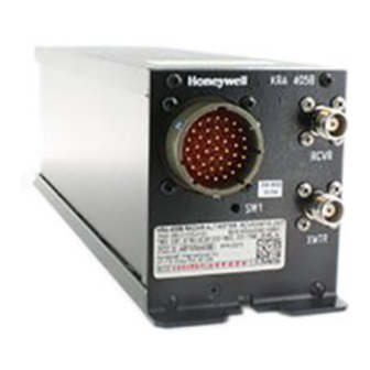
UNITS AND ACCESSORIES SUPPLIED 1.4.1 THE KRA 405 RADAR ALTIMETER SYSTEM COMPONENTS 1.4.1.A Bendix/King KRA 405 Radar Altimeter (R/T), P/N 066-01048-0000,-0002 (-0000 has been replaced by -0002). 1.4.1.B Bendix/King KNI 415 Radar Altimeter Indicator, P/N 066-03031-0000,-0001,- 0002,-0003,-0004; or KNI 416 Radar Altimeter Indicator, P/N 066-03044- 0000,-0001,-0002,-0003,-0004. - Page 13 The indicator with a black faceplate and NVG lighting is P/N 066-03031-0004, P/N 066-03044-0004. 1.4.1.C Bendix/King KA 54A Radar Altimeter Antenna (2 each), P/N 071-01501-0000. 1.4.1.D Bendix/King KRA 405 Radar Altimeter R/T Installation Kit (050-01391-0000) which includes: 050-01391-0000 INSTALLATION KIT --------------------------------------------------------------- SYMBOL...
-
Page 14: Accessories Required But Not Supplied
RELEASED FOR THE EXCLUSIVE USE BY: AIRCRAFT ELECTRONICS ASSOCIATION KRA 405 Array PW06B14-19SY Amphenol PT06A14-19SY(SR) 1.4.1.F Bendix/King KA 54A Radar Altimeter Antenna Installation Kit (050-02960- 0000) which includes: 050-02960-0000 KA54A INSTALL KIT --------------------------------------------------------------- SYMBOL PART NUMBER FIND NO DESCRIPTION -0000 --------------------------------------------------------------- 030-00108-0000 CONN TNC CA RG214... -
Page 15: Installation
Failure to provide cooling to the equipment will lead to increased avi- onics maintenance costs and may also void the Honeywell warranty. ALTITUDE TRIP ADJUSTMENT 2.3.1... -
Page 16: Altitude Trip Set Test Equipment (Audio Generator)
RELEASED FOR THE EXCLUSIVE USE BY: AIRCRAFT ELECTRONICS ASSOCIATION KRA 405 Three altitude trips are provided in the KRA 405 Radar Altimeter R/T (P/N 066-01048- 0002) and set at 250, 500 and 1200 feet. Should the customer elect to have these altitudes changed, the installing agency should follow the steps in paragraph 2.3.2. -
Page 17: Kra 405 System Installation
RELEASED FOR THE EXCLUSIVE USE BY: AIRCRAFT ELECTRONICS ASSOCIATION KRA 405 2.3.2.B.9 To adjust Altitude Trip #3, follow the procedures in steps 4 through 7 above using TP 613 and R653 in step 7. 2.3.2.B.10 Verify the trip adjustments by the following: 2.3.2.B.10.a Adjust the signal generator until the voltage at TP 506 is at least 1.50 volts above the highest trip point. -
Page 18: Approved Antennas
RELEASED FOR THE EXCLUSIVE USE BY: AIRCRAFT ELECTRONICS ASSOCIATION KRA 405 2.4.3 ANTENNAS 2.4.3.A Approved Antennas The KRA 405 Radar Altimeter System requires two antennas for a single system in- stallation. Since the system is CW, one antenna is used to transmit the signal and the other is used to receive the reflected signal. - Page 19 RELEASED FOR THE EXCLUSIVE USE BY: AIRCRAFT ELECTRONICS ASSOCIATION KRA 405 2.4.3.B.4 ANTENNAS MAY BE MOUNTED IN LINE OR SIDE-BY-SIDE, the former be- ing the best choice of the two. When using side-by-side installations, the an- tennas should be mounted on a flat surface of the aircraft. The angle between the antenna centerlines should be less than 6 deg.
- Page 20 RELEASED FOR THE EXCLUSIVE USE BY: AIRCRAFT ELECTRONICS ASSOCIATION KRA 405 prep #33 (P/N 016-01127-0000) to cleanse the metal of any residue left after removing paint or insulating material. Protect bare aluminum surfaces with Alodine 1001 (P/N 016-01128-0000) or equivalent prior to mounting antennas or bonding straps.
- Page 21 RELEASED FOR THE EXCLUSIVE USE BY: AIRCRAFT ELECTRONICS ASSOCIATION KRA 405 2.4.4.3 Antenna Height The antenna height above ground at touchdown is determined by information obtained in the aircraft manual or by actually measuring the height of the antenna when the air- craft is in touchdown configuration.
-
Page 22: Post Installation Tests
RELEASED FOR THE EXCLUSIVE USE BY: AIRCRAFT ELECTRONICS ASSOCIATION KRA 405 After selection of the AID, the proper pins on the KRA 405 R/T connector must be jum- pered. 2.4.4.5.A 40 foot AID: Jumper pins a and J. 2.4.4.5.B 57 foot AID: No jumpers are necessary. 2.4.4.6 Example Using Figure 2-8... -
Page 23: Rf Leakage Test Equipment (Microwave Absorber)
RELEASED FOR THE EXCLUSIVE USE BY: AIRCRAFT ELECTRONICS ASSOCIATION KRA 405 In most cases altimeter installations that closely follow the suggestions of paragraph 2.4.3 will need no special equipment to check the integrity of the system, and the first 5 steps of paragraph 2.5.2 are sufficient to determine proper altimeter operation. - Page 24 RELEASED FOR THE EXCLUSIVE USE BY: AIRCRAFT ELECTRONICS ASSOCIATION KRA 405 2.5.2.C.4 Slowly advance the DH but until the DH lamp lights. The bug should be set at 50 +/- 5 feet at this time. Continue increasing the DH but setting. The DH lamp should stay lit.
-
Page 25: Rf Output Test Equipment (Delay Line)
RELEASED FOR THE EXCLUSIVE USE BY: AIRCRAFT ELECTRONICS ASSOCIATION KRA 405 2.5.3.1.B Required Equipment The items listed below, or their electrical equivalent, may be used to conduct the tests in this section. TABLE 2-4 RF Output Test Equipment (Delay Line) TYPE CHARACTERISTICS REPRESENTATIVE MODELS... -
Page 26: If And Altitude Processor Test Equipment (Audio Generator)
RELEASED FOR THE EXCLUSIVE USE BY: AIRCRAFT ELECTRONICS ASSOCIATION KRA 405 2.5.3.2 Test Method 2 KRA 405 Radar Altimeter Post Installation Test Procedures using audio generator. 2.5.3.2.A Purpose of Test This test simulates altitudes of 0 to 2,500 ft to the IF and altitude processor. This test does not check the RF output, but may indicate poor coax cables and connectors. -
Page 27: Indicated Kni 415, Kni 416 Altitude (+/- 7%)
RELEASED FOR THE EXCLUSIVE USE BY: AIRCRAFT ELECTRONICS ASSOCIATION KRA 405 TABLE 2-6 Indicated KNI 415, KNI 416 Altitude (+/- 7%) MINIMUM (+/- 1%) 40 ft AID 57 ft AID ATTENUATION 100920 2500 ft 2491.5 ft 98920 2450 ft 2441.5 ft 88920 2200 ft 2191.5 ft... - Page 28 RELEASED FOR THE EXCLUSIVE USE BY: AIRCRAFT ELECTRONICS ASSOCIATION KRA 405 THIS PAGE RESERVED Rev 6, June 2003 IM 006-00104-0006.dwd Page 2-14...
- Page 29 BENDIX/KING KRA 405 FIGURE 2-1 KNI 415, KNI 416 Installation Drawing (Dwg No 155-05160-0000, Rev 1) Rev 6, June 2003 IM 006-00104-0006.dwd Page 2-15...
- Page 30 BENDIX/KING KRA 405 FIGURE 2-2 KRA 405 Installation Drawing (Dwg No 155-05153-0000, Rev 1) Rev 6, June 2003 IM 006-00104-0006.dwd Page 2-17...
- Page 31 RELEASED FOR THE EXCLUSIVE USE BY: AIRCRAFT ELECTRONICS ASSOCIATION KRA 405 FIGURE 2-3 Typical Antenna Installation For a Dual Radar Altimeter System (Sheet 1 of 2) Rev 6, June 2003 IM 006-00104-0006.dwd Page 2-19...
- Page 32 RELEASED FOR THE EXCLUSIVE USE BY: AIRCRAFT ELECTRONICS ASSOCIATION KRA 405 FIGURE 2-3 Typical Antenna Installation For a Dual Radar Altimeter System (Sheet 2 of 2) Rev 6, June 2003 IM 006-00104-0006.dwd Page 2-20...
- Page 33 BENDIX/KING KRA 405 FIGURE 2-4 KA 54 (Dorne Margolin Type DMPN 3-3/A) Antenna Outline and Mounting Drawing (Dwg No 155-05159-0000, Rev 1) Rev 6, June 2003 IM 006-00104-0006.dwd Page 2-21...
- Page 34 BENDIX/KING KRA 405 FIGURE 2-5 UBC (Type AD 43013-1) and Comant (Type 01-34-04531) Antenna Outline and Mounting Drawing (Dwg No 155-05166-0000, Rev 0) Rev 6, June 2003 IM 006-00104-0006.dwd Page 2-23...
- Page 35 BENDIX/KING KRA 405 FIGURE 2-6 Dorne Margolin (Type DMPN 3-4/A) Antenna Outline and Mounting Drawing (Dwg No 155-05167-0000, Rev 2) Rev 6, June 2003 IM 006-00104-0006.dwd Page 2-25...
- Page 36 BENDIX/KING KRA 405 FIGURE 2-7 KA 54A (Sensor Systems Type S67-2002) Antenna Outline and Mounting Drawing (Dwg No 071-01501-0000, Rev AC) Rev 6, June 2003 IM 006-00104-0006.dwd Page 2-27...
- Page 37 RELEASED FOR THE EXCLUSIVE USE BY: AIRCRAFT ELECTRONICS ASSOCIATION KRA 405 FIGURE 2-8 Aircraft Installation Delay (AID) and Installation Cable Length Chart Rev 6, June 2003 IM 006-00104-0006.dwd Page 2-29...
- Page 38 RELEASED FOR THE EXCLUSIVE USE BY: AIRCRAFT ELECTRONICS ASSOCIATION KRA 405 FIGURE 2-9 TNC Coax/ Connector Assembly (RG 393/U) (P/N 030-00108-0004) Rev 6, June 2003 IM 006-00104-0006.dwd Page 2-30...
- Page 39 RELEASED FOR THE EXCLUSIVE USE BY: AIRCRAFT ELECTRONICS ASSOCIATION KRA 405 FIGURE 2-10 Connector Pin Locations Rev 6, June 2003 IM 006-00104-0006.dwd Page 2-31...
-
Page 40: Kra 405 Altitude Trip Test Point And Adjustment Locations
RELEASED FOR THE EXCLUSIVE USE BY: AIRCRAFT ELECTRONICS ASSOCIATION KRA 405 FIGURE 2-11 KRA 405 Altitude Trip Test Point and Adjustment Locations Rev 6, June 2003 IM 006-00104-0006.dwd Page 2-32... -
Page 41: Kra 405 Test Equipment Setup
RELEASED FOR THE EXCLUSIVE USE BY: AIRCRAFT ELECTRONICS ASSOCIATION KRA 405 FIGURE 2-12 KRA 405 Test Equipment Setup Rev 6, June 2003 IM 006-00104-0006.dwd Page 2-33... - Page 42 RELEASED FOR THE EXCLUSIVE USE BY: AIRCRAFT ELECTRONICS ASSOCIATION KRA 405 FIGURE 2-13 External Sonalert w/ 15 Second DH Audio Fader Rev 6, June 2003 IM 006-00104-0006.dwd Page 2-34...
-
Page 43: Kra 405 Radar Altimeter System Interconnect
BENDIX/KING KRA 405 FIGURE 2-14 KRA 405 Radar Altimeter System Interconnect (Dwg No 155-01153-0000, Rev 9) Rev 6, June 2003 IM 006-00104-0006.dwd Page 2-35... -
Page 44: General
RELEASED FOR THE EXCLUSIVE USE BY: AIRCRAFT ELECTRONICS ASSOCIATION KRA 405 SECTION III OPERATION GENERAL The KNI 415 and KNI 416 Radar Altimeter Indicators are shown in Figure 3-1 and are discussed below. Altitude Scale: The KNI 415 scale gives accurate altitude indications from -20 to +2000 feet. - Page 45 RELEASED FOR THE EXCLUSIVE USE BY: AIRCRAFT ELECTRONICS ASSOCIATION KRA 405 3.2.1.A Turn on primary aircraft power. 3.2.1.B Adjust the DH knob on the KNI 415, KNI 416 Radar Altimeter Indicator to set the DH but to 25 feet. 3.2.1.C Depress the TEST button.
-
Page 46: Emergency Operation
RELEASED FOR THE EXCLUSIVE USE BY: AIRCRAFT ELECTRONICS ASSOCIATION KRA 405 DH lamp lights to alert the pilot that a decision is to be made. The DH lamp may then be turned off by pressing the lamp in. EMERGENCY OPERATION 3.3.1 SELF TEST ERRORS 3.3.1.A... - Page 47 RELEASED FOR THE EXCLUSIVE USE BY: AIRCRAFT ELECTRONICS ASSOCIATION KRA 405 FIGURE 3-1 KNI 415 Control Functions Rev 6, June 2003 IM 006-00104-0006.dwd Page 3-4...
- Page 48 RELEASED FOR THE EXCLUSIVE USE BY: AIRCRAFT ELECTRONICS ASSOCIATION KRA 405 FIGURE 3-2 KNI 416 Control Functions Rev 6, June 2003 IM 006-00104-0006.dwd Page 3-5...
- Page 49 RELEASED FOR THE EXCLUSIVE USE BY: AIRCRAFT ELECTRONICS ASSOCIATION KRA 405 THIS PAGE RESERVED Rev 6, June 2003 IM 006-00104-0006.dwd Page 3-6...
Need help?
Do you have a question about the BENDIX/KING KRA 405 and is the answer not in the manual?
Questions and answers