Table of Contents
Advertisement
Quick Links
Download this manual
See also:
System Manual
CONTENTS
Typical Venting System Components...............................................
Connecting Power Venter to Appliance..........................................
Maintenance......................................................................
READ THESE INSTRUCTIONS CAREFULLY AND COMPLETELY BEFORE PROCEEDING WITH THE INSTALLATION.
This device MUST be installed by a qualifi ed agency in accordance with the manufacturer's installation instructions. The defi nition of
a qualifi ed agency is: any individual, fi rm, corporation or company which either in person or through a representative is engaged
in, and is responsible for, the installation and operation of HVAC appliances, who is experienced in such work, familiar with all the
precautions required, and has complied with all the requirements of the authority having jurisdiction.
Installed By:
POWER VENTER
Model: PVE Series
Operation..............................................................................
Sizing...........................................................................
Instructions..........................................................
Venter...............................................................
Instructions..............................................................
Adjustments..........................................................................
Inspection.........................................................
List.......................................................................
Information......................................................
Please retain these instructions after installation.
Phone:
www.fi eldcontrols.com
Page
2
3
3,4
5,6
6,7
7
7
8
8,9
9,10
10
11
Installation Date:
Advertisement
Table of Contents

Subscribe to Our Youtube Channel
Related Manuals for Field Controls PVE-100


Summary of Contents for Field Controls PVE-100
-
Page 1: Table Of Contents
POWER VENTER Model: PVE Series CONTENTS Page Typical Venting System Components..........System Operation................Power Venter Sizing................Installation Safety Instructions............Installation Power Venter............... Connecting Power Venter to Appliance.......... General Wiring Instructions.............. Airfl ow Adjustments................General Installation Inspection............Maintenance..............9,10 Replacement Parts List............... -
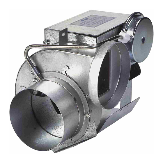
Page 2: Typical Venting System Components
1 - CK Series Control Kit (Not included) DESCRIPTION OF POWER VENTER MODELS Figure 1 UNIT DIMENSIONS (inches) ELECTRICAL DATA Model Inlet/ Thermal Volts Watts AMPS Outlet Protection PVE-100 7.50 7.75 7.00 4.00 3000 PVE-300 7.50 9.25 7.00 4.00 3000 PVE-600 8.75... -
Page 3: System Operation
CONTROL KITS The following are the most commonly used Control Kits. CK-20F: For operation with 30 millivolt or 750 millivolt gas-fi red water heaters, gas-fi red space heaters and gas-fi red pool or spa heaters with an internally mounted thermostat. Includes a non-adjust- able post purge timer. - Page 4 MAXIMUM EQUIVALENT HORIZONTAL PIPE LENGTH (FEET) Venter Model and Vent Pipe Diameter BTU/HR Input PVE-100 PVE-300 PVE-600 PVE-1200 3" 4" 4" 5" 6" 5" 6" 8" 8" 10" 25,000 55,000 70,000 100,000 145,000 220,000 310,000 400,000 520,000 610,000 700,000 900,000...
-
Page 5: Installation Safety Instructions
For gas appliances use a Field Controls Type MG-1 Barometric Draft Control. For oil appliances use a Field Controls Type M or RC Barometric Draft Control. Gas-fi red draft induced systems should have a single- acting or double-acting barometric draft control installed. -
Page 6: Installation Of Power Venter
INSTALLATION OF POWER VENTER CAUTION: Failure to install, maintain, and/or operate the power venting system in accordance with manufac- turer's instructions will result in conditions which may produce bodily injury and/or property damage. 1. Remove power venter from box and inspect unit for damage. If the carton has been crushed or mutilated, check unit very carefully for damage. -
Page 7: Connecting Power Venter To Appliance
GENERAL WIRING INSTRUCTIONS The PVE-100, 300, 600, and 1200 are designed to be used with either millivolt, 24 VAC, or 120 VAC appliances when used with the appropriate controls. For use on a millivolt controlled system a Field Controls HWK-6 or an appropriate Control Kit is required. -
Page 8: Airfl Ow Adjustments
If this occurs, a post purge system may be required. If so, use a Field Controls PPC-5 Electronic Post Purge. Before installing, refer to the General Installation Inspection to check for negative pressure problems in the building. -
Page 9: General Installation Inspection
GENERAL INSTALLATION INSPECTION Recommended procedures for safety inspection of an appliance in accordance with the National Fuel Gas Code ANSI Z223.1. The following procedure will help evaluate the venting system. It is intended as a guide to aid in determining that the venting system is properly installed and is in a safe condition for continuous use. -
Page 10: Maintenance
The following items are available for replacement, if necessary. REPLACEMENT PARTS LIST Description Part Number PVE-100 Motor 46032000 PVE-300 Motor 46032000 PVE-600 Motor 46083300 PVE-1200 Motor 46226500 PVE-100 Blower Wheel 46080100 PVE-300 Blower Wheel 46033400 PVE-600 Blower Wheel 46089400 PVE-1200 Blower Wheel 46124000 page 10... -
Page 11: System Operational Information
INITIAL BURNER AND VENTING SYSTEM OPERATIONAL INFORMATION List for each operating appliance on the sidewall venting system, as a guide for tune-up or service information. FOR GAS-FIRED EQUIPMENT Heating Appliance BTU/HR Input _____________________________________________________________ Gas Valve Operation Pressure _______________________________________________________________ Vent System Draft Above Draft Hood __________________________________________________________ or Below Barometric Draft Control____________________________________________________________ Measurement ________________________________________________________________________ CO Measurement _________________________________________________________________________... - Page 12 WARRANTY For warranty about this or any Field Controls product, visit: www.fi eldcontrols.com/warranty Phone: 252.522.3031 • Fax: 252.522.0214 www.fieldcontrols.com © Field Controls, LLC P/N 46115300 Rev F 04/15...
Need help?
Do you have a question about the PVE-100 and is the answer not in the manual?
Questions and answers