
Subscribe to Our Youtube Channel
Related Manuals for Field Controls 46115300


Summary of Contents for Field Controls 46115300
-
Page 1: Table Of Contents
PVE SERIES POWER VENTER SYSTEM MANUAL Contents Page Typical Venting System Components System Operation III. Power Venter Sizing IV. Installation Safety Instructions Installation of Power Venter VI. Connecting Power Venter to Appliance VII. General Wiring Instructions VIII. Airflow Adjustments IX. General Installation Inspection Maintenance 9,10 XI. -
Page 2: Typical Venting System Components
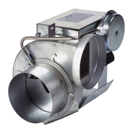
TYPICAL VENTING SYSTEM COMPONENTS: 1 - PVE Series Power Venter 1 - SWH-1 Series Sidewall Vent Hood (Not included) 1 - CK Series Control Kit (Not included) A. D ESCRIPTION OF OWER ENTER ODELS Unit Dimensions (inches) ELECTRICAL DATA MODEL INLET/ THERMAL "H"... -
Page 3: System Operation
C. CONTROL KITS: The following are the most commonly used Control Kits. CK-20F: For operation with 30 millivolt or 750 millivolt gas-fired water heaters, gas-fired space heaters and gas-fired pool or spa heaters with an internally mounted thermostat. Includes a non-adjustable post purge timer. Use the CK-22 for an adjustable post purge timer. - Page 4 MAXIMUM EQUIVALENT HORIZONTAL PIPE LENGTH (FEET) VENTER MODEL AND VENT PIPE DIAMETER BTU/HR INPUT PVE-100 PVE-300 PVE-600 PVE-1200 3" 4" 4" 5" 6" 5" 6" 8" 8" 10" 25,000 55,000 70,000 100,000 145,000 220,000 310,000 400,000 520,000 610,000 700,000 900,000 1,000,000 1,250,000 A.
-
Page 5: Installation Safety Instructions
Reducer or increaser ratio (d/D) small diameter divided by the larger diameter. Example 4" to 8" reducer, the reducer ratio is d/D = 4/8 = 1/2. To estimate the equivalent foot length for the fitting, use the smaller pipe diameter for the equivalent length figure. Example 4" to 8" reducer; the reducer ratio is 1/2 and the smaller pipe diameter is 4". -
Page 6: Installation Of Power Venter
For gas appliances use a Field Controls Type MG-1 Barometric Draft Control. For oil appliances use a Field Controls Type M or RC Barometric Draft Control. Gas-fired draft induced systems should have a single-acting or double-acting barometric draft control installed. -
Page 7: Connecting Power Venter To Appliance
VAC appliances when used with the appropriate controls. For use on a millivolt controlled system a Field Controls HWK-6 or an appropriate Control Kit is required. For use on a 24 VAC or 120 VAC controlled system a Control Kit must be used. Refer to the installation manuals for the HWK-6 and individual Control Kits for wiring instructions. -
Page 8: Airflow Adjustments
If this occurs, a post purge system may be required. If so, use a Field Controls PPC-5 Electronic Post Purge. Before installing, refer to the General Installation Inspection to check for negative pressure problems in the building. -
Page 9: Maintenance
procedure may be necessary to determine safe operation of the equipment. If it is determined that a condition exists which could result in unsafe operation, the appliance should be shut off and the owner advised of the unsafe condition. Corrections must be made before the appliance is put into continuous operation. -
Page 10: Replacement Parts List
System Safety Devices: With the heating system operating disconnect the pressure sensing tube from the pressure switch on the CK kit. This should stop the burner operation. Re- connecting the tube will relight the burner. For 30 millivolt operating systems, disconnect one lead of the spill switch circuit from the thermocouple junction block. -
Page 11: System Operational Information
XII. INITIAL BURNER AND VENTING SYSTEM OPERATIONAL INFORMATION List for each operating appliance on the sidewall venting system, as a guide for tune-up or service information. FOR GAS-FIRED EQUIPMENT Heating Appliance BTU-HR Input ___________________________________________________ Gas Valve Operation Pressure _____________________________________________________ Vent System Draft Above Draft Hood ________________________________________________ or below Barometric Draft Control___________________________________________________ Measurement ______________________________________________________________ CO Measurement _______________________________________________________________... - Page 12 P/N 46115300 Rev. D Page 12...
Need help?
Do you have a question about the 46115300 and is the answer not in the manual?
Questions and answers