Advertisement
Quick Links
COMBUSTION AIR SYSTEM
This product is designed for use with any natural gas or LP burning furnace, water heater, or boiler with a
24 VAC control system. It may be used with a millivolt powered system with additional hardware. It may
also be used with more than one appliance. The CAS unit mechanically draws air into a structure and
disperses it near the combustion air intake of an appliance. If an optional Vacuum Relief Valve (VRV) is
used, the incoming air is tempered before entering the structure's airspace. Refer to Diagrams A and B for
guidance in setting up the CAS system based on the size and length of the connecting ductwork and the
input rating of the appliance.
READ THESE INSTRUCTIONS CAREFULLY AND COMPLETELY BEFORE PROCEEDING WITH THE INSTALLATION.
This device MUST be installed by a qualified agency in accordance with the manufacturer's installation instructions. The definition of
a qualified agency is: any individual, firm, corporation or company which either in person or through a representative is engaged
in, and is responsible for, the installation and operation of HVAC appliances, who is experienced in such work, familiar with all the
precautions required, and has complied with all the requirements of the authority having jurisdiction.
Installed By:
MODEL: CAS-4
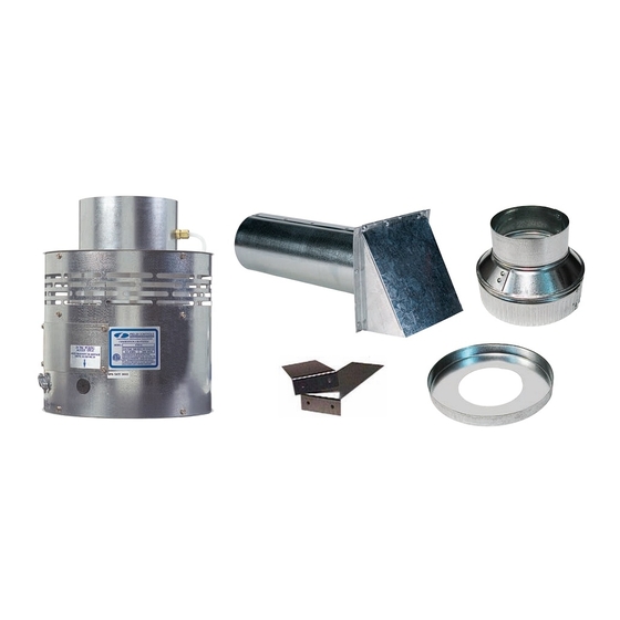
ITEMS INCLUDED IN KIT:
1- Motorized Blower
1- 4" galvanized intake air Vent Hood
2- Mounting brackets to secure the CAS to a wall
2- Wire/conduit connectors
1- 4" x 6" Pipe Increaser Fitting
1- 6" Orifice Ring
1- Instruction Sheet
1- High/Low Motor Speed Switch
Please retain these instructions after installation.
Phone:
www.fieldcontrols.com
Installation Date:
Advertisement

Related Manuals for Field Controls CAS-4


Summary of Contents for Field Controls CAS-4
- Page 1 COMBUSTION AIR SYSTEM MODEL: CAS-4 This product is designed for use with any natural gas or LP burning furnace, water heater, or boiler with a 24 VAC control system. It may be used with a millivolt powered system with additional hardware. It may also be used with more than one appliance.
- Page 2 GENERAL SYSTEM OPERATION The thermostat (wall thermostat, or aquastat) calls for heat and energizes a relay which activates the CAS unit. After the CAS fan has come up to speed, an internal air pressure switch closes and completes the circuit to allow the burner to fire. If the appliance is power vented, the venter and CAS activate simultaneously.
- Page 3 Table 1 TOTAL INPUT OF APPLIANCE MAXIMUM EQUIVALENT FEET OF INSTALLATION 4" Duct And Hood w/ 4" Duct and 4" 6" Duct and 6" CAS-4, 4mV Gas Restrictor Intake Air Hood Intake Air Hood (BTU/hr.) 50,000 75,000...
- Page 4 Diagram A LOW SPEED SIZING CHART OIL INPUT FIRING RATE (gallons per hour) (1 gallon oil/hr = 140,000 BTU/hr.) 0.50 1.00 1.50 2.00 2.50 6" Duct & Hood 4" Duct & Hood 4" Duct & Hood w/ Orifice GAS INPUT FIRING RATE (1000 BTU/hr.) Diagram B page 4...
- Page 5 INSTALLATION PLACEMENT OF THE CAS UNIT The motorized CAS unit should be located on a flat horizontal surface within the same space as the appliance and within 3' of the combustion air intake as possible. Two mounting brackets are provided for securing the unit against a solid structure, such as a wall, column, or the side of the appliance itself.
- Page 6 The references to various series of control kits implies that any kit in that series may be used. If further information or additional wiring diagrams are needed please consult Field Controls' technical support. INTERNAL WIRING CONNECTIONS FOR THE CAS UNIT Refer to Figure 4 for the internal wiring of the CAS-4 unit.
- Page 7 White Common Black White White White Black Figure 6- Power Vent Single 24V Furnace Black White Black Figure 7- Chimney Vent 24V Furnace and 30mV Water Heater With CK-20FV or CK-20FG page 7...
- Page 8 Figure 9- Power Vent Single 24V Boiler Figure 8- Chimney Vent 24V Boiler page 8...
- Page 9 Figure 10- Chimney Vent Two 24V Gas Appliances With CAC-24 page 9...
- Page 10 Note: Pressure sensing tubes of CK Control Kits needs to be “teed” together the hooked Note: DIP 1 needs to be up to SWG, DI, or PV Unit. “teed” into pressure sensing tube on CAS 4. Figure 11- One Power Venter Two 24V Gas Appliances With DIP-1 page 10...
-
Page 11: Maintenance
If this is necessary, take note of the positions and locations of whatever items that may need to be removed to replace other items. If in doubt, please consult Field Controls Technical Support at 1-800-742-8368. ITEM DESCRIPTION... -
Page 12: Limited Warranty
Field Controls Direct Vent Systems (FDVS), Field Oil Vent Kits (FOVP), and ComboVents (CV). Field Controls warrants that the products listed below shall be free from defects in material and workmanship under normal use for the limited period indicated, from the date of purchase by the consumer, subject to the provisions 1-8 below.
Need help?
Do you have a question about the CAS-4 and is the answer not in the manual?
Questions and answers