Table of Contents
Advertisement
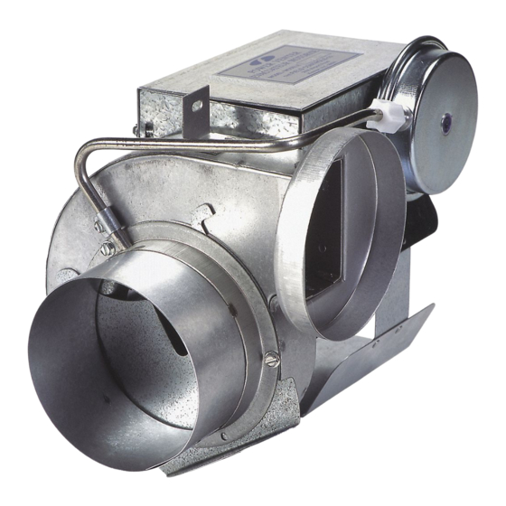
POWER VENTER SYSTEM
Included is one ETL LISTED power venter to be used for side wall venting of a single 24 VAC controlled
furnace, boiler, or water heater which burns natural or LP gas. The PVG may also be used to vent a single
24 VAC controlled gas fi red furnace or boiler and a 30 millivolt residential gas fi red water heater.
ITEMS INCLUDED:
1- PVG-100, 300, or 600 POWER VENTER with
pre-wired integral 24 VAC Relay/Timer, factory
set Draft Proving Switch, and direct access
Terminal Blocks.
1- Installation Instruction Sheet
OPTIONAL SYSTEM COMPONENTS:
(NOT INCLUDED)
Side Wall Vent Hood
Spill Switches
Barometric Draft Control
READ THESE INSTRUCTIONS CAREFULLY AND COMPLETELY BEFORE PROCEEDING WITH THE INSTALLATION.
This device MUST be installed by a qualifi ed agency in accordance with the manufacturer's installation instructions. The defi nition of
a qualifi ed agency is: any individual, fi rm, corporation or company which either in person or through a representative is engaged
in, and is responsible for, the installation and operation of HVAC appliances, who is experienced in such work, familiar with all the
precautions required, and has complied with all the requirements of the authority having jurisdiction.
Installed By:
Model: PVG-100, PVG-300, PVG-600
Please retain these instructions after installation.
Phone:
www.fi eldcontrols.com
CONTENTS
System Operation................................................
Power Venter Sizing............................................
Installation Safety Instructions............................
Installation of Power Venter................................
General Wiring Instructions...............................
Airfl ow Adjustments............................................
Adjusting Thermostat Anticipator.......................
General Installation Inspection..........................
System Control Check Procedures.....................
Troubleshooting Tips...........................................
Maintenance........................................................
Replacement Parts List.........................................
Multiple Venting Systems....................................
Venting System Operational Information..........
Installation Date:
PAGE
2
3, 4
4, 5
5, 6
7
8
8
8
9
9
9
10
10, 11
11
P/N 46246300 Rev M 04/20
Advertisement
Table of Contents

Subscribe to Our Youtube Channel
Related Manuals for Field Controls PVG-100


Summary of Contents for Field Controls PVG-100
-
Page 1: Table Of Contents
24 VAC controlled gas fi red furnace or boiler and a 30 millivolt residential gas fi red water heater. CONTENTS PAGE ITEMS INCLUDED: System Operation..........1- PVG-100, 300, or 600 POWER VENTER with Power Venter Sizing..........3, 4 pre-wired integral 24 VAC Relay/Timer, factory Installation Safety Instructions...... -
Page 2: System Operation
UNIT SPECIFICATIONS Figure 1 Table 1 UNIT DIMENSIONS (INCHES) ELECTRICAL RATINGS MODEL I/O* WATT TP** PVG-100 10.0 ⁄ 3000 PVG-300 11.5 ⁄ 3000 PVG-600 8.75 12.0 ⁄ 3000 *Inlet and outlet diameter **Thermally protected motor SIDEWALL VENT HOODS (Model SWH-1) Sidewall vent hoods are available in the following sizes. -
Page 3: Power Venter Sizing
The choke plate can be adjusted to compensate for the diff erence. Table 2 MAXIMUM EQUIVALENT HORIZONTAL PIPE LENGTH (FEET) VENTER MODEL NUMBER AND VENT PIPE DIAMETER BTU/HR INPUT PVG-100 PVG-300 PVG-600 3" 4" 4"... -
Page 4: Installation Safety Instructions
INSTALLATION SAFETY INSTRUCTIONS CAUTION: This device must be installed by a qualifi ed installer in accordance with the manufacturer's installation instructions. Appliances should have a minimum of 75% combustion effi ciency or have a maximum measured fl ue gas temperature of 550°F at the inlet of the venter. 1. -
Page 5: Installation Of Power Venter
Use a Field Controls Type MG-1 Barometric Draft Control. Gas-fi red draft induced systems should have a single-acting or double-acting barometric draft control installed. - Page 6 NOTE: Do not enclose the space between the plates on the outside of the vent hood or between the inner and outer pipe of the vent hood. This might cause overheating of the wall structure. Local codes might require fencing around the vent hood outlet. VENTER LOCATION Install the power venter onto the vent hood inlet or as close to the vent hood inlet as possible.
-
Page 7: General Wiring Instructions
3. Wire the switch into the low voltage thermostat circuit. Refer to the appropriate wiring diagram in this manual. 4. After installation, check the amperage through the thermostat circuit and adjust the anticipator if necessary. CAUTION: The GSK-3 is a manual reset switch. Investigate the system thoroughly for the cause of any shut down and correct the problem before resetting the GSK-3 and restarting the system. -
Page 8: Airfl Ow Adjustments
ADJUSTING THERMOSTAT ANTICIPATOR If connecting the Power Venter system to a gas appliance with a thermostat anticipator, refer to the following to make adjustments. Disconnect one side of the thermostat circuit at the gas valve or burner control, and connect an ampere meter into the circuit. With the system running, take an amperage reading on the circuit. -
Page 9: System Control Check Procedures
Motor: Inspect the motor once a year - motor should rotate freely. To prolong the life of the PVG-600 motor, it must be lubricated with six drops of SWG Superlube, Part #46226200, annually. The PVG-100 and PVG-300 have sealed ball bearings, and therefore do not need to be oiled. -
Page 10: Replacement Parts List
REPLACEMENT PARTS LIST The following items are available for replacement, if necessary. REPLACEMENT PARTS LIST DESCRIPTION PVG-100 PVG-300 PVG-600 Motor 46032000 46032000 46083300 Blower Wheel 46080100 46033400 46089400 24 VAC Relay 46282800 46282800 46282800 Pressure Switch 602602001 602602002 602602003 MULTIPLE VENTING SYSTEMS 1. -
Page 11: Venting System Operational Information
Diagram C PVG WIRING FOR MULTIPLE 24VAC APPLIANCES PVG WIRING FOR MULTIPLE 24VAC APPLIANCES AIR PRESSURE SWITCH AIR PRESSURE SWITCH PVG JUNCTION BOX PVG JUNCTION BOX PLASTIC PLASTIC BUSHING BUSHING RELAY/TIMER RELAY/TIMER MOTOR MOTOR LEADS LEADS L N M L N M APPLIANCE APPLIANCE CONNECTIONS... - Page 12 This manual may be downloaded and printed from the Field Controls website (www.fi eldcontrols.com) This manual may be downloaded and printed from the Field Controls website (www.fi eldcontrols.com) This manual may be downloaded and printed from the Field Controls website (www.fi eldcontrols.com) This manual may be downloaded and printed from the Field Controls website (www.fi eldcontrols.com)
Need help?
Do you have a question about the PVG-100 and is the answer not in the manual?
Questions and answers
Draft control weighted damper
The function of the Field Controls PVG-100 draft control weighted damper is to regulate proper airflow and control fluctuations in the system’s airflow during operation. This ensures appliance efficiency and safe venting by responding to changes such as wind loads, house depressurization, and seasonal ventilation differences.
This answer is automatically generated