Table of Contents
Advertisement
Available languages
Available languages
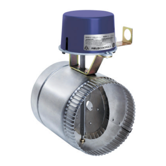
Field Controls (GVD) gas vent damper was developed to reduce off cycle venting losses through boilers and
draft hoods. When the boiler is in the standby mode heat escapes up the chimney. The heat comes from the
boiler and the condition space. To significantly reduce these losses install a Field Gas Vent Damper. The
damper is installed between the vent or chimney and as close to the draft hood as practical. When properly
installed the damper opens before the burner fires and closes after the burner shuts off. The electrical
circuits in this product are designed not to override the existing limit and safety controls of the boiler.
CAUTION
appliance is equipped with an intermittent or direct
ignition system. Failure to follow these instructions can
cause odor problems and minor property damage due
to moisture. Do not install on standing pilot systems.
GAS VENT DAMPER
Model: GVD-4 through 12
The plug is installed only if the
English........... Page 1
Français......... Page 13
Tape Plug
Here
Advertisement
Table of Contents
Troubleshooting

Related Manuals for Field Controls 46352700


Summary of Contents for Field Controls 46352700
- Page 1 Model: GVD-4 through 12 Field Controls (GVD) gas vent damper was developed to reduce off cycle venting losses through boilers and draft hoods. When the boiler is in the standby mode heat escapes up the chimney. The heat comes from the boiler and the condition space.
- Page 2 OPERATION When the boiler receives a call for heat, the damper rotates to the open position before the burner circuit is energized. If the damper does not rotate to the open position, the burner circuit will not be energized. When properly installed, the electrical circuits in this product are designed not to override the existing limit and safety controls of the appliance.
- Page 3 UNPACKING INSTRUCTIONS 1. The Field Controls GVD Series Gas Vent Damper is packaged in a single carton containing an assembled GVD, instruction manual and a plug. NOTE: Some OEM supplied units have the wiring harness attached. 2. Inspect for damage prior to the installation.
- Page 4 Safety Inspection 1. Conduct a gas leakage test of the appliance piping and control system downstream of the shutoff valve in the supply line to the appliance. 2. Visually inspect the venting system for proper size, horizontal pitch and vent termination, and determine there is no blockage or restriction, leakage, corrosion and other deficiencies which could cause an unsafe condition.
- Page 5 HOW TO INSTALL AN ADDITIONAL GAS VALVE Determine if the appliance has a redundant gas valve. If it has a redundant gas valve proceed to install the damper assembly. WARNING: If the appliance does not have a redundant gas valve, an additional gas valve or a redundant gas valve must be installed.
- Page 6 INSTALLATION OF THE UNIT WARNING: Install the automatic vent damper to service only the single appliance for which it is intended. See Figure 4. If improperly installed a hazardous condition such as an explosion or carbon monoxide poisoning could result. WARNING: To be used only with an appliance bearing a marking showing the make and model of the device.
- Page 7 PPLIANCE IRING 1. To locate the vent damper wire harness (if supplied) receptacle on the appliance, refer to the appliance manufacturer instruction manual and follow accordingly. (See Figures 5,6,7) 2. The wire harness shall be securely fastened thru the conduit bracket, located on the vent damper motor assembly.
- Page 8 The following steps are to be followed in making the modifications: 1. Perform a safety inspection of the existing appliance installation. See PRE-INSTALLATION INSPECTIONS section for the recommended procedure for such a safety inspection. 2. Shut off all gas and electricity to the appliance. To shut off gas use the shutoff valve in the supply line to the appliance. 3.
- Page 9 WIRING All electrical work and materials used in the vent damper installation shall be in accordance with local electrical codes. In the absence of codes, consult the National Electrical Code. To avoid damage to the room thermostat heat anticipator turn off the electrical power supply to the appliance before proceeding with the wiring.
- Page 10 PROBLEM POSSIBLE CAUSE RECOMMENDED SOLUTION 1. Off on limit (120VAC) 1. Turn limit on. 2. Bad Transformer. 2. Replace transformer. 3. Loose or broken connections. 3. Tighten, repair or replace connection. NO POWER 4. Blown fuse or circuit breaker. 4. Replace fuse or reset circuit breaker. Between 4&1 5.
- Page 11 ROUBLE HOOTING ITH A UMPER IRE IN LACE PROBLEM POSSIBLE CAUSE RECOMMENDED SOLUTION 1. Is gas turned on. 1. Make sure gas is on. 2. Operating limit, pressure control or 2. Make sure operating limit, pressure POWER ON low water cut off not on. control or low water cut off is on.
- Page 12 Page 12...
- Page 13 Modèles : GVD-4 à 12 Field Controls a mis au point les registres d’évent à gaz de série GVD afin de réduire les pertes de chaleur par le conduit d’évacuation de la chaudière et du coupe-tirage pendant les cycles d’arrêt. Lorsque la chaudière est en mode d’attente, la chaleur provenant de la chaudière et de l’espace d’air conditionné...
- Page 14 NSTRUCTIONS DE DÉBALLAGE 1. Le registre d’évent à gaz Field Controls de série GVD est livré dans une seule caisse en carton contenant le registre assemblé, la notice technique et un bouchon. NOTA : Certains appareils vendus par des constructeurs OEM sont livrés avec un câble d’alimentation.
- Page 15 12. Ce registre ne doit être installé que sur un appareil au gaz homologué, raccordé à une cheminée ou un conduit d’évacuation préfabriqués obéissant à une norme reconnue, ou à une cheminée de maçonnerie ou de béton dont le revêtement interne est approuvé...
- Page 16 Inspection de sécurité 1. Effectuer un test de repérage de fuite de gaz sur la tuyauterie et le système de régulation de l’appareil en aval du robinet d’arrêt du tuyau d’alimentation de l’appareil de chauffage. 2. Faire une inspection visuelle du système d’évacuation afin de vérifier si les dimensions et la pente horizontale du système ainsi que l’extrémité...
- Page 17 INSTALLATION D’UN ROBINET D’ADMISSION DE GAZ ADDITIONNEL Vérifier si l’appareil est équipé d’un robinet de gaz redondant. Dans l’affirmative, procéder à l’installation du registre. AVERTISSEMENT – Si l’appareil n’est pas équipé d’un robinet de gaz redondant, on doit y installer un robinet de gaz additionnel ou un robinet redondant.
- Page 18 INSTALLATION DU REGISTRE AVERTISSEMENT – Installer le registre automatique de manière qu’il ne desserve que l’appareil auquel il est destiné (Schéma 4). Une installation incorrecte pourrait créer des conditions dangereuses susceptibles de provoquer notamment une explosion ou un empoisonnement au monoxyde de carbone. AVERTISSEMENT –...
- Page 19 ’ ÂBLAGE ÉLECTRIQUE DE L APPAREIL DE CHAUFFAGE 1. Consulter la notice technique du fabricant de l’appareil de chauffage pour connaître l’emplacement de la prise sur laquelle doit être branché (s’il est fourni) le câble d’alimentation du registre. (Schémas 5, 6 et 7) 2.
- Page 20 La procédure suivante doit être observée pour effectuer les modifications. 1. Effectuer une inspection de sécurité de l’appareil en suivant la procédure décrite à la rubrique INSPECTIONS PRÉALABLES À L’INSTALLATION. 2. Couper l’arrivée de gaz (au moyen du robinet d’arrêt installé sur le tuyau d’alimentation de l’appareil) et l’alimentation électrique de l’appareil.
- Page 21 15. Consigne applicable uniquement aux générateurs de chaleur – Vérifier le fonctionnement du limiteur et de la commande du ventilateur. On peut vérifier le fonctionnement du limiteur en obturant la prise d’air de circulation ou en coupant provisoirement l’alimentation électrique du ventilateur et en vérifiant si le limiteur déclenche la coupure de l’alimentation du brûleur principal. 16.
- Page 22 PROBLÈMES ET SOLUTIONS ATTENTION – Lorsque les commandes font l’objet de travaux d’entretien et de réparation, étiqueter tous les fils avant de les débrancher. Une erreur de branchement peut entraîner un fonctionnement incorrect ou dangereux. Éviter de manoeuvrer le clapet du registre à...
- Page 23 ÉPANNAGE AVEC UN CAVALIER IMPORTANT – Le registre doit être OUVERT avant que le brûleur ne s’allume. PROBLÈME CAUSE POSSIBLE SOLUTION RECOMMANDÉE 1. Robinet d’admission de gaz 1. Ouvrir le robinet de gaz. fermé. 2. Limiteur, régulateur de pression 2. Mettre le limiteur, le régulateur ou ou interrupteur de bas niveau l’interrupteur en fonction.
- Page 24 P/N 46352700 Rev B 09/01 Page 24...
Need help?
Do you have a question about the 46352700 and is the answer not in the manual?
Questions and answers