Table of Contents
Advertisement
Quick Links
COMBUSTION AIR SYSTEM
This product is designed for use with any natural gas or LP burning furnace, water heater, or boiler with a 24
VAC control system. The CAS-4 may be used with one 24V-controlled combustion heating appliance and one
30mV standing-pilot gas water heater with the use of an additional CK-20 series control kit. Additional 120V or
24V-controlled appliances may also be served by the CAS-4 with the addition of one CAC-120 or CAC-24 control
kit per each additional appliance (see note)*. The CAS unit mechanically draws air into a structure and disperses it
near the combustion air intake of an appliance. Refer to Diagrams A and B for guidance in setting up the CAS
system based on the size and length of the connecting ductwork and the input rating of the appliance.
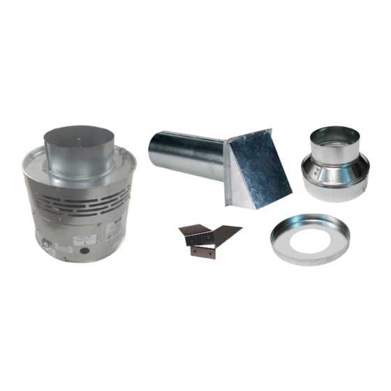
ITEMS INCLUDED IN KIT:
1- Motorized Blower
2- Mounting brackets to secure the CAS to a wall
1- 4" x 6" Pipe Increaser Fitting
1- Instruction Sheet
WARNING! CONNECTIONS TO MULTIPLE APPLIANCES MUST FOLLOW INSTALLATION INSTRUCTION
WARNING! CONNECTIONS TO MULTIPLE APPLIANCES MUST FOLLOW INSTALLATION INSTRUCTION
WIRING DIAGRAMS. FOR HELP CALL 1-800-742-8368.
WIRING DIAGRAMS. FOR HELP CALL 1-800-742-8368.
*NOTE: The model CAS-4 design has recently been changed. Please note that there are diff erences in construction,
operation, and installation of this CAS as compared to legacy product. Also, note that for multiple-appliance
installations, each additional appliance will require either a CAC-24 or CAC-120 control kit be provided for that
appliance. Installations with one heating appliance and one 30mV gas water heater will require an additional CK-20
series control kit in addition to the CAS-4.
READ THESE INSTRUCTIONS CAREFULLY AND COMPLETELY BEFORE PROCEEDING WITH THE INSTALLATION.
This device MUST be installed by a qualifi ed agency in accordance with the manufacturer's installation instructions. The defi nition of
a qualifi ed agency is: any individual, fi rm, corporation or company which either in person or through a representative is engaged
in, and is responsible for, the installation and operation of HVAC appliances, who is experienced in such work, familiar with all the
precautions required, and has complied with all the requirements of the authority having jurisdiction.
Installed By:
MODEL: CAS-4
Please retain these instructions after installation.
Phone:
www.fi eldcontrols.com
1- 4" galvanized intake air Vent Hood
2- Wire/conduit connectors
1- 6" Orifi ce Ring
1- High/Low Motor Speed Switch
Installation Date:
P/N 46284600 Rev L 09/19
Advertisement
Table of Contents

Related Manuals for Field Controls FAN IN A CAN CAS4


Summary of Contents for Field Controls FAN IN A CAN CAS4
- Page 1 COMBUSTION AIR SYSTEM MODEL: CAS-4 This product is designed for use with any natural gas or LP burning furnace, water heater, or boiler with a 24 VAC control system. The CAS-4 may be used with one 24V-controlled combustion heating appliance and one 30mV standing-pilot gas water heater with the use of an additional CK-20 series control kit.
-
Page 2: General System Operation
GENERAL SYSTEM OPERATION 1. The thermostat (wall thermostat, or aquastat) calls for heat and energizes a relay which activates the CAS unit. After the CAS fan has come up to speed and air fl ow into the CAS inlet is estabished, an internal air pressure switch closes and completes the circuit to allow the burner to fi re. - Page 3 EXAMPLE: A gas fi red appliance fi ring at 100,000 BTU/hr. where the CAS unit needs to be placed 30 equivalent feet from the intake hood. From Diagram A or B, the point at 100,000 BTU/hr. on the Gas Firing Rate scale and 30 equivalent feet falls in the 4"...
- Page 4 Diagram A LOW SPEED SIZING CHART OIL INPUT FIRING RATE (gallons per hour) (1 gallon oil/hr = 140,000 BTU/hr.) 0.50 1.00 1.50 2.00 2.50 6" Duct & Hood 4" Duct & Hood 4" Duct & Hood w/ Orifice GAS INPUT FIRING RATE (1000 BTU/hr.) Diagram B page 4 of 12 P/N 46284600 Rev L 09/19...
-
Page 5: Installation Of Duct
INSTALLATION PLACEMENT OF THE CAS UNIT The motorized CAS unit should be located on a fl at horizontal surface within the same space as the appliance and within 3' of the combustion air intake as possible. Two mounting brackets are provided for securing the unit against a solid structure, such as a wall, column, or the side of the appliance itself. -
Page 6: Wiring Instructions
The references to various series of control kits implies that any kit in that series may be used. If further information or additional wiring diagrams are needed please consult Field Controls' technical support. INTERNAL WIRING CONNECTIONS FOR THE CAS UNIT Refer to Figure 4 for the internal wiring of the CAS-4 unit. - Page 7 Figure 5- Power Vent Single 24V Furnace Figure 6- Chimney Vent 24V Furnace and 30mV Water Heater With CK-20FV or CK-20FG page 7 of 12 P/N 46284600 Rev L 09/19...
- Page 8 P/N 46284600 Rev L 09/19 page 8 of 12...
- Page 9 Figure 9 - Chimney Vent Two 24V Gas Appliances With CAC-24 page 9 of 12 P/N 46284600 Rev L 09/19...
- Page 10 Figure 10- One Power Venter Two 24V Gas Appliances page 10 of 12 P/N 46284600 Rev L 09/19...
-
Page 11: Maintenance
If this is necessary, take note of the positions and locations of whatever items that may need to be removed to replace other items. If in doubt, please consult Field Controls Technical Support at 1-800-742-8368. ITEM DESCRIPTION... -
Page 12: Warranty
This manual may be downloaded and printed from the Field Controls website (www.fi eldcontrols.com) This manual may be downloaded and printed from the Field Controls website (www.fi eldcontrols.com) WARRANTY WARRANTY For warranty information about this or any Field Controls product, visit: For warranty information about this or any Field Controls product, visit: www.fi eldcontrols.com...
Need help?
Do you have a question about the FAN IN A CAN CAS4 and is the answer not in the manual?
Questions and answers