Table of Contents
Advertisement
Quick Links
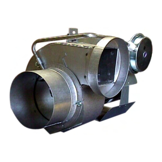
Included is one ETL and cETL listed Power Venter to be used primarily with a
single 120VAC controlled oil fired furnace, boiler, or water heater. The PVO
may be used to common vent multiple appliances with the addition of a Control
Kit. Please consult Field Control's Technical Support for other options.
TYPICAL VENTING SYSTEM COMPONENTS
One PVO Series Power Venter with pre-wired controls; adjustable post
purge relay timer, adjustable draft proving switch, direct access terminal
blocks, and piping tee for multiple appliance systems.
• Side Wall Vent Hood (Not included)
• CK-Series Control Kit for multiple appliance venting (Not Included)
This device MUST be installed by a qualified agency in accordance with the manufacturers installation
instructions.
The definition of a qualified agency is: any individual, firm, corporation or company which either in person or through a representative is
engaged in, and is responsible for, the installation and operation of gas appliances, who is experienced in such work, familiar with all
the precautions required, and has complied with the requirements of the authority having jurisdiction.
POWER VENTER SYSTEM
Model: PVO-300, PVO-600
C
ONTENTS
DO NOT DESTROY
THESE INSTRUCTIONS MUST REMAIN WITH EQUIPMENT
2630 Airport Road · Kinston, NC 28504
Phone: 252-522-3031· Fax: 252-522-0214
• Spill Switches (Not included)
www.fieldcontrols.com
P
AGE
2
2
3
4
5
5-6
7
7
7
7
8
8
9
10
10
Advertisement
Table of Contents

Related Manuals for Field Controls 46311800


Summary of Contents for Field Controls 46311800
-
Page 1: Table Of Contents
POWER VENTER SYSTEM Model: PVO-300, PVO-600 Included is one ETL and cETL listed Power Venter to be used primarily with a single 120VAC controlled oil fired furnace, boiler, or water heater. The PVO may be used to common vent multiple appliances with the addition of a Control Kit. -
Page 2: Unit Specifications
UNIT SPECIFICATIONS (See Table 1 and Figure 1) Table 1 UNIT DIMENSIONS (INCHES) MODEL “H” “W” “D” I/O* PVO-300 7.50 9.25 7.00 PVO-600 8.75 9.75 8.50 Inlet and outlet diameter. ELECTRICAL RATINGS MODEL WATT TP** Figure 1 PVO-300 3000 PVO-600 3000 Thermally protected motor. -
Page 3: Power Venter Sizing
POWER VENTER SIZING In order to choose the correct size power venter for a particular installation, the total input firing rate and total equivalent length of vent pipe to be used must be known. Refer to Table 2 to determine the maximum allowable equivalent feet of pipe for each model used with the pipe diameters shown. -
Page 4: Installation Safety Instructions
Use a Field Controls Type MG-1 Barometric Draft Control. Gas-fired draft induced systems should have a single-acting or double-acting barometric draft control installed. -
Page 5: Installation Of Power Venter
INSTALLATION OF POWER VENTER CAUTION: Failure to install, maintain and/or operate the power venting system in accordance with manufacturer's instructions will result in conditions which may produce bodily injury and/or property damage. 1. Remove power venter from box and inspect unit for damage. If the carton has been crushed or mutilated, check unit very carefully for damage. - Page 6 Diagram B Diagram C Page 6...
-
Page 7: Airflow Adjustments
ULTIPLE PPLIANCE YSTEMS When using one PVO power venter to common vent more than one appliance, a Control Kit is required for each additional appliance. 1. Connect the negative pressure port of each air pressure fan proving switch on all Control Kits being used to the provided tee mounted on the PVO. -
Page 8: General Installation Inspection
GENERAL INSTALLATION INSPECTION Follow recommended procedures for safety inspection of a heating appliance in accordance with the National Fuel Gas Code A.N.S.I. Z223.1. The following procedure will help in evaluation of the venting system. It is intended as a guide to aid in determining that the appliance is properly installed and is in a safe condition for continuous use. - Page 9 PV SERIES POWER VENTER: VERTICAL VENTING OPTION Diagram D illustrates correct and incorrect installation of PV series venter in vertical vent configuration (except PVE- 1200). The correct installation maintains the required vertical position of the pressure switch; the incorrect installation does not.
-
Page 10: Replacement Parts List
REPLACEMENT PARTS LIST The following items are available for replacement, if necessary. REPLACEMENT PARTS LIST DESCRIPTION PVO-300 PVO-600 Motor 46032000 46083300 Blower Wheel 46033400 46089400 Post Purge Relay Timer 46144700 4614470 Pressure Switch 46311000 46311000 VENTING SYSTEM OPERATIONAL INFORMATION Date: Oil Burner Nozzle Size Oil Burner Operating Pressure Pump Operating Vacuum Pressure... - Page 11 NOTES Page 11...
- Page 12 Page 12 P/N 46311800 Rev D 10/06...
Need help?
Do you have a question about the 46311800 and is the answer not in the manual?
Questions and answers