Table of Contents
Advertisement
Available languages
Available languages
Quick Links
Advertisement
Chapters
Table of Contents

Subscribe to Our Youtube Channel
Related Manuals for Sentiotec VitaMy 164


Summary of Contents for Sentiotec VitaMy 164
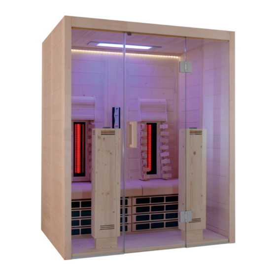
- Page 1 Infrarotkabine VitaMy 164 164 x 120 x 202 cm MONTAGE- UND GEBRAUCHSANWEISUNG Deutsch Symbolfoto VITAMY-164-B / 1-037-765: VitaMy 164 Basic VITAMY-164-BT / 1-037-767: VitaMy 164 BT VITAMY-164-S&L / 1-037-768: VitaMy 164 S&L Version 05/15 Ident-Nr. 1-038-133...
-
Page 2: Table Of Contents
3.3. Lieferumfang VitaMy 164 S&L 3.4. Produktfunktionen 4. Montage der Infrarotkabine VitaMy 164 4.1. Benötigtes Werkzeug 4.2. Stückliste Infrarotkabine VitaMy 164 Basic / BT / S&L 4.3. Montage der Kabine 4.4. Einbau der Infrarot-Steuerung 4.5. Einbau des Bluetooth Moduls (nur VitaMy 164 BT) 4.6. -
Page 3: Zu Dieser Anleitung
Sie sie in der Nähe der Infrarotkabine auf. So können Sie jederzeit Informationen zu Ihrer Sicherheit und zur Bedienung nachlesen. Sie finden diese Montage- und Gebrauchsanweisung auch im Download- bereich unserer Webseite auf www.sentiotec.com/downloads. Symbole in Warnhinweisen In dieser Montage- und Gebrauchsanweisung ist vor Tätigkeiten, von denen eine Gefahr ausgeht, ein Warnhinweis angebracht. -
Page 4: Wichtige Hinweise Zu Ihrer Sicherheit
Montage- und Gebrauchsanweisung S. 4/44 2. Wichtige Hinweise zu Ihrer Sicherheit Die Infrarotkabine ist nach anerkannten sicherheitstechnischen Regeln gebaut. Dennoch können bei der Verwendung Gefahren entstehen. Befolgen Sie deshalb die folgenden Sicherheitshinweise und die speziellen Warnhinweise in den einzelnen Kapiteln. 2.1. - Page 5 Montage- und Gebrauchsanweisung S. 5/44 ● Die Kabine darf nicht von Kindern unter 8 Jahren verwendet werden. ● Die Kabine darf von Kindern über 8 Jahren, von Personen mit verringerten psychischen, sensorischen oder mentalen Fähig- keiten und von Personen mit Mangel an Erfahrung und Wissen unter folgenden Bedingungen verwendet werden: –...
-
Page 6: Produktbeschreibung
Montage- und Gebrauchsanweisung S. 6/44 3. Produktbeschreibung 3.1. Lieferumfang VitaMy 164 Basic ● 1x Infrarotkabine VitaMy 164 ● 1x 1-037-357 / Leistungsteil wave.com4 Infra ● 1x 1-012-222 / Bedienteil wave.com4 Infra ● 1x 1-009-265 / Netzanschlussleitung Infrarot 2,5m ● 2x 1-028-862 / Kabel GST18i/3s – GST18i/3B 0,5m ●... -
Page 7: Produktfunktionen
Mobiltelefone, Tablets, Notebooks etc., verwendet werden. Der Verstärker ist im Bluetooth-Modul bereits integriert. sound & light Farblampe (nur Ausführung VitaMy 164 S&L) Die Farblampe sound & light ermöglicht das Abspielen von Musik mittels USB- Stick und Beleuchtung der Kabinen mit verschiedensten Farben. -
Page 8: Montage Der Infrarotkabine Vitamy 164
● Akkuschrauber mit Bits für Kreuzschrauben und Torx ● Rollmaßband ● Wasserwaage ● Durchschlag oder Holzklötzchen 12 mm ● Imbus 1,5 mm 4.2. Stückliste Infrarotkabine VitaMy 164 Basic / BT / S&L Stückliste -VitaMy 1-037-804 Bodenrahmen hinten - 1640 x 40 x 90 mm 1-037-808... - Page 9 U-Leisten für IR-Wärmeplatte links - 410 x 60 x 65 mm 1-038-003 U-Leisten für IR-Wärmeplatte rechts - 410 x 60 x 65 mm 1-038-020 IR-Wärmeplatte VitaMy 164 - 738 x 420 x 43 mm 1-038-004 Aussteifungsleiste für Wärmeplatten - 1560 x 40 x 25 mm 1-038-031...
-
Page 10: Montage Der Kabine
Montage- und Gebrauchsanweisung S. 10/44 4.3. Montage der Kabine Beachten Sie den Grundriss auf Seite 43. Montage des Bodenrahmens Abb. 1: Auflegen der drei Bodenrahmen-Elemente Abb. 2: Bodenelemente verbinden Schlagen Sie die Kunstoffschwalben vorsichtig mit einem Hammer, an den beiden Ecken des Bodenrahmens ein, bis diese bündig mit der Nut des Elements sind. - Page 11 Montage- und Gebrauchsanweisung S. 11/44 Montage der Wandelemente Beginnen Sie die Montage der Wandelemente mit den Wandelementen W2 und W3 bzw. W4 und W5 (siehe Kapitel Grundriss auf Seite 43). Die Wandelemente werden mit den „Multiclips“ mit den Eckstehern verbunden. Achten Sie darauf, dass die Elemente mit der Öffnung für den Infrarotstrahler W3 u.
- Page 12 Montage- und Gebrauchsanweisung S. 12/44 Abb. 4: Wandelemente mit Ecksteher verbinden Stecken Sie den Ecksteher von oben nach unten auf die Wandelemente. Ach- ten Sie dabei auf die korrekte Ausrichtung der „Multiclips“ (siehe Abb. 4). Der Ecksteher muss bündig mit den Wandelementen sein. Abb.
- Page 13 Montage- und Gebrauchsanweisung S. 13/44 Abb. 6: Elektroelement einsetzen Nachdem Sie das Elektroelement eingesetzt haben, fahren Sie mit der zweiten Ecke fort. Abb. 7: Fertig montierte Rückwand WORLD OF WELLNESS...
- Page 14 Montage- und Gebrauchsanweisung S. 14/44 Abb. 8: Montage seitliche Wandelemente W1 und W6 Abb. 9: Montage der beiden vorderen Ecksteher mit Nut für Glas WORLD OF WELLNESS...
- Page 15 Montage- und Gebrauchsanweisung S. 15/44 Abb. 10: Montierte Wandelemente WORLD OF WELLNESS...
- Page 16 Montage- und Gebrauchsanweisung S. 16/44 Montage der Glaselemente Stecken Sie das U-Profil bündig auf die Glasplatte. Achten Sie dabei auf den bün- digen Abschluss der Profile mit dem Glas an jener Seite, an der die Tür sein wird. WARNUNG! Kleben Sie nachdem die Kabine korrekt positioniert ist, die U-Profile mit Silikon oder Montagekleber an den Boden.
- Page 17 Montage- und Gebrauchsanweisung S. 17/44 Abb. 12: Einsetzen der Glasscheibe in die Nut des Eckstehers Schieben Sie das Glas vorsichtig in die Nut des Eckstehers. Führen Sie dies für beide Glas-Seitenteile durch. Abb. 13: Montage Massivleiste über der Glasfront Für die Montage der Massivleiste die beiden vorderen Ecksteher nach außen drücken und die Massivleiste mittles Dübelverbindungen einsetzen.
- Page 18 Montage- und Gebrauchsanweisung S. 18/44 Abb. 15: Fixieren der Massivleiste Die Massivleiste durch zusammendrücken der seitlichen Wandelemente fixieren, bis die Dübel nicht mehr sichtbar sind. Montage der Dachelemente Kontrollieren Sie die rechtwinkelige Ausrichtung der Kabine in den Ecken oder messen mit dem Rollband die beiden Diagonalen der Kabine, wenn diese gleich lang sind, ist die Kabine korrekt ausgerichtet.
- Page 19 Montage- und Gebrauchsanweisung S. 19/44 Abb. 16: Dachauflageleisten Abb. 17: Einlegen Dachelement hinten mit Lüfterausschnitt Abb. 18: Einlegen Dachelemente vorne WORLD OF WELLNESS...
- Page 20 Montage- und Gebrauchsanweisung S. 20/44 Nachdem die Dachelemente eingelegt wurden, müssen diese mit der Dachauf- lageleiste verschraubt werden. Abb. 19: Befestigen der Dachelemente Schrauben 14 Stk: 3,5 x 35 Montage der Türe Abb. 20: Aufsetzen der Türdichtung Die Dichtung wird auf das Glaselement aufgesetzt, welches keine Bohrungen für die Türbeschläge besitzt.
- Page 21 Montage- und Gebrauchsanweisung S. 21/44 Abb. 21: Montage Türgriff Setzen Sie zuerst die beiden Silikoneinlagen in die Bohrungen für den Türgriff am Glaselement ein. Danach verschrauben Sie die beiden Griffe vorsichtig miteinander. Schrauben 2 Stk: 3,5 x 70 Die untere Bohrung des Türgriffs ist in 92,5 cm Höhe. Die Türgriffe werden von außen miteinander verschraubt.
- Page 22 Montage- und Gebrauchsanweisung S. 22/44 Abb. 22: Montage Türbeschläge 1 Schrauben Sie die beiden Türbeschläge am Fix-Glaselement fest, achten sie dabei auf die gerade Ausrichtung der Beschläge und darauf, dass die Öffnung der Türe nach außen erfolgt. Die Ausrichtung der Beschläge wird durch die Justierung / Drehung der beiden Kunstoffringe vorgenommen.
- Page 23 Montage- und Gebrauchsanweisung S. 23/44 Abb. 24: Montage Türmagnet Der Magnet für die Tür muss auf jener Seite sein, an der die Türe öffnet. Montieren Sie den Magnet ggfs. auf die entsprechende Seite. Schneiden Sie die Türdichtung über der Ausnehmung für den Magnet mit einem scharfen Messer durch und legen die Ausnehmung frei.
- Page 24 Montage- und Gebrauchsanweisung S. 24/44 Abb. 26: Fertige Kabinenwände und Dachelemente Montage des Kabinenbodens Abb. 27: Befestigung für Kabinenboden montieren WORLD OF WELLNESS...
- Page 25 Montage- und Gebrauchsanweisung S. 25/44 Abb. 28: Kabinenboden einlegen Montage der Frontstrahler Abb. 29: Frontstrahler fixieren Achten Sie darauf, dass die Kabel der Frontstrahler frei am Boden liegen und nicht durch den Kabinenboden eingeklemmt oder beschädigt werden. WORLD OF WELLNESS...
- Page 26 Montage- und Gebrauchsanweisung S. 26/44 Nachdem die Strahler am Boden eingerastet sind, fixieren Sie diese jeweils mit einer Drehung um 90° an den Imbusschrauben im Uhrzeigersinn an den vier Befestigungspunkten. Abb. 30: Fronstrahler fixieren Abb. 31: Einlegen der Specksteinschalen WORLD OF WELLNESS...
- Page 27 Montage- und Gebrauchsanweisung S. 27/44 Montage der Bankauflage und der IR-Wärmeplatten Abb. 32: Montage der Bankauflage Schrauben 6 Stk: 5 x 70 Schrauben Sie links und rechts in der Kabine die Bankauflagen und am Elekt- roelement die Bankauflage-Leiste mit je 2 Schrauben fest. Abb.
- Page 28 S. 28/44 Abb. 34: Einsetzen der IR-Wärmeplatte VitaMy 164 Setzen Sie die den beide IR-Wärmeplatten VitaMy 164 in die U-Leisten ein. Die Ausnehmung dient zur Durchführung der Leitung des Frontstrahles (siehe Abb. 35) Achten Sie beim Einsetzen der IR-Wärmeplatte auf die Kabel der Schalter, diese dürfen nicht eingeklemmt oder beschädigt werden.
- Page 29 Montage- und Gebrauchsanweisung S. 29/44 Montage der Entlüftung Abb. 36: Montage der Entlüftung Schrauben Sie das Basiselement der Entlüftung mit den 3 beiliegend Schrauben fest. Schrauben Sie anschließend das Holzteller ein und sichern Sie die Schraube von außen mit der Kunststoffkappe. WORLD OF WELLNESS...
- Page 30 Montage- und Gebrauchsanweisung S. 30/44 Montage der LED Abdeckleiste Abb. 37: Montage der LED-Abdeckleiste Schrauben 3 Stk: 3,5 x 50 Schrauben Sie die LED-Abdeckleiste mit 3 Schrauben von außen an der Decke fest. Abb. 38: Einkleben des LED Stripes Kleben Sie den LED Stripe in die Abdeckleiste ein. Der Stecker der LED Stripes muss genügend weit durch die Öffnung in der Decke reichen (siehe Abb.
- Page 31 Montage- und Gebrauchsanweisung S. 31/44 Anschluss des LED Stripes Abb. 39: Verbinden des LED Stripes mit der Steuerung Geben Sie das Netzteil der LED Beleuchtung unter die Bank. Führen Sie die Anschlussleitung und den Netzstecker durch die Öffnung in der Rückwand nach außen.
- Page 32 Montage- und Gebrauchsanweisung S. 32/44 Montage der Rückenstrahler Abb. 41: Rückenstrahler (Infrarot-Strahler ECO 350) montieren Schrauben 8 Stk: 3 x 18 Setzten Sie die beiden Strahler von innen in den Ausschnitt ein. Schrauben Sie die Strahler mit je 4 Schrauben fest. VORSICHT! Achten Sie darauf, dass der Anschlusskasten der Strahler auf der Oberseite ist!
-
Page 33: Einbau Der Infrarot-Steuerung
Montage- und Gebrauchsanweisung S. 33/44 4.4. Einbau der Infrarot-Steuerung Beachten Sie für die Montage, Inbetriebnahme und Bedienung die An- leitung welche der Steuerung beiliegt. Die Betriebsart „Raumtemperaturregelung“ wird von der beiliegenden Steuerung nicht unterstützt. Montage des Bedienteils Montieren Sie das Bedienteil an die vorgesehene Stelle in der Rückwand der Kabine. - Page 34 Montage- und Gebrauchsanweisung S. 34/44 Anschluss des Leistungsteils Das Leistungsteil der Steuerung wird unter der Bank der Kabine platziert und wie folgt angeschlossen. Abb. 44: Anschlüsse Leistungsteil Stecker Beschreibung wave.com4 Infra Bedienteil IR-Heizgruppe 1 IR-Heizgruppe 2 Netzanschluss Lüfteranschluss (schwarz) - optional Lichtanschluss (grün) WORLD OF WELLNESS...
- Page 35 Montage- und Gebrauchsanweisung S. 35/44 Zuordnung der Heizgruppen Das Leistungsteil der Steuerung wird unter der Bank der Kabine platziert und wie folgt angeschlossen. Heizgruppe 1: Frontstahler links, Rückenstrahler links, Wadenstrahler links (über Schalter) Heizgruppe 2: Frontstahler rechts, Rückenstrahler rechts, Wadenstrahler rechts (über Schalter) Die Anordnung kann beinahe beliebig den eigenen Wünschen angepasst werden.
-
Page 36: Einbau Des Bluetooth Moduls (Nur Vitamy 164 Bt)
Montage- und Gebrauchsanweisung S. 36/44 4.5. Einbau des Bluetooth Moduls (nur VitaMy 164 BT) Beachten Sie für die Montage, Inbetriebnahme und Bedienung die An- leitung, welche dem Bluetooth-Modul und den Excitern beiliegt. Montage des Bedienteils Montieren sie das Bedienteil an die vorgesehe Stelle in der Rückwand der Kabine. - Page 37 Montage- und Gebrauchsanweisung S. 37/44 Anschluss des Bedienteils Schließen Sie die Exciter und das Netzteil lt. Anleitung am Bedienteil an. Das Netzteil muss sich außerhalbe der Kabine befinden. Abb. 48: Anschluss des Bedienteils WORLD OF WELLNESS...
-
Page 38: Einbau Der Sound & Light (Nur Vitamy 164 S&L)
Montage- und Gebrauchsanweisung S. 38/44 4.6. Einbau der sound & light (nur VitaMy 164 S&L) Beachten Sie für die Montage, Inbetriebnahme und Bedienung die An- leitung welche der sound & light Farblampe beiliegt. Montage des Bedienteils und des USB-Docks Montieren sie das Bedienteil und das USB-Dock an die vorgesehen Stellen in der Rückwand der Kabine. -
Page 39: Montage Der Bank
Montage- und Gebrauchsanweisung S. 39/44 Anschluss des Bedienteils und der Farblampe Schließen Sie das Bedienteil, USB-Dock und die Farblampe lt. beiliegender Anleitung am sound & light Leistungsteil an. Montieren Sie das Leistungsteil vorzugsweise außen auf der Kabinendecke oder unter der Bank. 4.7. -
Page 40: Montage Der Abstandleisten Der Rückwand
Montage- und Gebrauchsanweisung S. 40/44 4.8. Montage der Abstandleisten der Rückwand Schrauben Sie die Abstandleisten an der Rückwand fest, wahlweise bündig oder bis zu 10 cm nach innen versetzt. Abb. 52: Montage Abstandleisten Rückwand Schrauben 4 Stk: 4 x 70 4.9. - Page 41 Montage- und Gebrauchsanweisung S. 41/44 Entfernen Sie die Montageschablone und stecken Sie abschließend die Rücken- lehnen von oben nach unten auf die Halterungen bis diese einrasten. Abb. 54: Montage Kopfstützen Schrauben Sie die Halterungen mit mindestens 1 cm Abstand zur Oberkante des Rahmens, seitlich bündig mit der Halterung der Rückenlehnen, fest.
-
Page 42: Reinigung Und Wartung
Wasser. ● Reinigen Sie die Kabine und die elektronischen Komponenten nicht zu feucht. 5.2. Wartung Die Infrarotkabine VitaMy 164 ist wartungsfrei. 6. Problemlösung ● Bei Problemen, die in den Montageanweisungen nicht ausführlich genug behandelt werden, wenden Sie sich zu Ihrer eigenen Sicherheit an Ihren Lieferanten. -
Page 43: Technische Daten
- 25 °C bis + 70 °C Umgebungstemperatur: 20 °C bis + 30 °C Luftfeuchtigkeit: max. 95% 9. Grundriss Da Holz ein Naturprodukt ist, sind geringfügige Maßabweichungen möglich. VitaMy 164 Basic / BT / S&L 164 x 120 x 202 cm WORLD OF WELLNESS... - Page 44 NOTIZEN / APPUNTI / NOTES / NOTE / NOTITIES ………………………………………………….....………………………………………………………………... ……………………………………………………………..……………………………………………………………... …………………………………………………………….....………………………………………………………... …………………………………………………….....………………………………………………………………... ……………………………………………………………..……………………………………………………………... ……………………………………………………………..……………………………………………………………... ……………………………………………………………..…………………………………………………………... …………………………………………………………….....………………………………………………………... …………………………………………………………….....………………………………………………………... …………………………………………………………….....………………………………………………………... …………………………………………………………….....………………………………………………………... …………………………………………………………….....………………………………………………………..…………………………………………………………….....………………………………………………………... …………………………………………………………….....………………………………………………………... …………………………………………………………….....………………………………………………………... …………………………………………………………….....………………………………………………………... …………………………………………………………….....………………………………………………………... …………………………………………………………….....………………………………………………………... …………………………………………………………….....………………………………………………………... WORLD OF WELLNESS...
- Page 45 Infrared cabin VitaMy 164 164 x 120 x 202 cm INSTRUCTIONS FOR INSTALLATION AND USE English Symbol photo VITAMY-164-B / 1-037-765: VitaMy 164 Basic VITAMY-164-BT / 1-037-767: VitaMy 164 BT VITAMY-164-S&L / 1-037-768: VitaMy 164 S&L Version 05/15 Ident. no. 1-038-133...
- Page 46 3.4. Product functions 4. Installation of the VitaMy 164 infrared cabin 4.1. Necessary tools 4.2. Infrared cabine VitaMy 164 Basic / BT / S&L parts list 4.3. Cabin installation 4.4. Installation of the infrared control 4.5. Installation of the Bluetooth module (only VitaMy 164 BT) 4.6.
-
Page 47: About This Instruction Manual
These installation and operating instructions can also be found in the downloads section of our website: www.sentiotec.com/downloads. Symbols used for warning notices In these instructions for installation and use, a warning notice located next to an activity indicates that this activity poses a risk. -
Page 48: Important Information For Your Safety
Instructions for installation and use p. 4/44 2. Important information for your safety The infrared cabin has been produced in accordance with the safety regulations applicable for technical units. However, hazards may occur during use. Therefore adhere to the following safety informa- tion and the specific warning notices in the individual chapters. - Page 49 Instructions for installation and use p. 5/44 ● The cabin must not be used by children under 8 years old. ● The cabin may be used by children above 8 years old, by persons with limited psychological, sensory or mental capabilities or by persons with lack of experience/knowledge only when: –...
-
Page 50: Product Description
Instructions for installation and use p. 6/44 3. Product description 3.1. Scope of delivery VitaMy 164 Basic ● 1x Infrared cabine VitaMy 164 ● 1x 1-037-357 / Power unit wave.com4 Infra ● 1x 1-012-222 / Control panel wave.com4 Infra ● 1x 1-009-265 / Power supply cord infrared 2.5m ●... -
Page 51: Product Functions
The amplifier is already integrated in the Bluetooth module. sound & light colour light (only version VitaMy 164 S&L) The sound & light colour light lets music be played via a USB stick and the cabins be lit with different colours. -
Page 52: Installation Of The Vitamy 164 Infrared Cabin
● water level ● drift punch or wooden blocks 12 mm ● Allen 1.5 mm 4.2. Infrared cabine VitaMy 164 Basic / BT / S&L parts list Parts List - VitaMy 164 1-037-804 Rear floor frame - 1640 x 40 x 90 mm... - Page 53 1-038-003 U-Strip for IR thermal plate right - 410 x 60 x 65 mm 1-038-020 IR thermal plate VitaMy 164 - 738 x 420 x 43 mm 1-038-004 Stiffener bar for thermal plate - 1560 x 40 x 25 mm...
-
Page 54: Cabin Installation
Instructions for installation and use p. 10/44 4.3. Cabin installation Observe the layout on page 43. Installing the floor frame Fig. 1: Placing the three floor frame elements Fig. 2: Connect the floor frame elements Hit the plastic swallows gently with a hammer at the two corners of the floor frame until they are flush with the groove of the element. - Page 55 Instructions for installation and use p. 11/44 Wall element installation Begin the installation of the wall elements with Wall Elements W2 and W3 or W4 and W5 respectively (see the chapter Layout on page 43). The wall elements are connected with the "multi-clips" with the corner posts. Make sure that the elements with the opening for the infrared radiators W3 and W4 are used at the back of the cabin.
- Page 56 Instructions for installation and use p. 12/44 Fig. 4: Connect the wall element with the corner post Insert the corner post from top to bottom on the wall elements. When doing so, pay attention to the correct alignment of the "multi-clips" (see Fig. Abb. 4). The corner post has to be flush with the wall elements.
- Page 57 Instructions for installation and use p. 13/44 Fig. 6: Install the electrical element in place After you have put the electric element in place, continue with the second corner. Fig. 7: Pre-assembled rear wall WORLD OF WELLNESS...
- Page 58 Instructions for installation and use p. 14/44 Fig. 8: Installation of side wall elements W1 and W6 Fig. 9: Installation of the two front corner posts with a groove for glass WORLD OF WELLNESS...
- Page 59 Instructions for installation and use p. 15/44 Fig. 10: Installed wall elements WORLD OF WELLNESS...
- Page 60 Instructions for installation and use p. 16/44 Glass element installation Insert the U-profile flush to the glass plate. When doing so, pay attention to the flush meeting of the profiles with the glass on the side where the door will be. WARNING! After the cabin has been positioned correctly, glue the U-profiles with silicone or installation glue to the floor.
- Page 61 Instructions for installation and use p. 17/44 Fig. 12: Inserting the glass sheet in the groove of the corner post Slide the glass gently into the groove of corner post. Do this for both glass side panels. Fig. 13: Installing the skirting over the glass front To install the skirting, press the two front corner posts outwards and insert the skirting by means of dowel joints.
- Page 62 Instructions for installation and use p. 18/44 Fig. 15: Attaching the skirting Attach skirting by squeezing the side wall elements until the anchors are no longer visible. Roof element installation Check the right angle alignment of the cabin in the corners or use the measuring tape to measure the two diagonals of the cabin;...
- Page 63 Instructions for installation and use p. 19/44 Fig. 16: Roof support slats Fig. 17: Installing the roof element in the back with the fan cut-out Fig. 18: Installing the roof element in the front WORLD OF WELLNESS...
- Page 64 Instructions for installation and use p. 20/44 After the roof elements have been inserted, they have to be screwed in with the roof support slat. Fig. 19: Attaching the roof element Screws 14 units: 3.5 x 35 Door installation Fig. 20: Installing the door insulation strips The insulation is placed on the glass element which does not have any holes for the door fittings.
- Page 65 Instructions for installation and use p. 21/44 Fig. 21: Door handle installation First, set the two silicone inserts in the holes for the door handle in the glass element. Then, screw the two handles together carefully. Screws 2 units: 3.5 x 70 The bottom hole of the door handle is at a height of 92.5 cm.
- Page 66 Instructions for installation and use p. 22/44 Fig. 22: Installation of Door Fitting 1 Screw the two door fittings onto the fix-glass element, making sure of the straight alignment of the fittings and that the door opens to the outside. The fittings are aligned through the adjustment/rotation of the two plastic rings.
- Page 67 Instructions for installation and use p. 23/44 Fig. 24: Door magnet installation The magnet for the door has to be on the side to which the door opens. Mount the magnet on the appropriate side, if appropriate. Cut the door insulation over the recess for the magnet with a sharp knife and expose the recess.
- Page 68 Instructions for installation and use p. 24/44 Fig. 26: Completed wall elements and roof elements Installing the cabin floor Fig. 27: Install the attachment for the cabin floor WORLD OF WELLNESS...
- Page 69 Instructions for installation and use p. 25/44 Fig. 28: Put the cabin floor in place Front radiator installation Fig. 29: Attach the front radiator in place Make sure that the cables of the front radiator are exposed at the bottom and are not pinched or damaged by the cabin floor.
- Page 70 Instructions for installation and use p. 26/44 After the radiators are locked in at the bottom, attach each one firmly with a 90° rotation on the Allen screws in a clockwise direction at the four attachment points. Fig. 30: Attach the front radiator in place Fig.
- Page 71 Instructions for installation and use p. 27/44 Installation of the bench cushion and the IR thermal plate Fig. 32: Installation of the bench cushion Screws 6 units: 5 x 70 Screw in the bench cushion left and right in the cabin as well as the bench cushion bar on the electric element with 2 screws each.
- Page 72 28/44 Fig. 34: Installation of the IR thermal plate VitaMy 164 Install the two IR thermal plates VitaMy 164 in the U-strips. The recess is used to perform the management of the front beam (see Fig. 35) When inserting the IR thermal plate, pay attention to the cable of the switch;...
- Page 73 Instructions for installation and use p. 29/44 Ventilation installation Fig. 36: Ventilation installation Screw together the base element of the vent and the 3 enclosed screws. Then screw the wooden plate into place and secure the screw from the outside with the plastic cap.
- Page 74 Instructions for installation and use p. 30/44 Installation of the LED cover strip Fig. 37: Installation of the LED cover strip Screws 3 units: 3.5 x 50 Use 3 screws to attach the LED cover strip to the ceiling from the outside. Fig.
- Page 75 Instructions for installation and use p. 31/44 Connecting the LED strips Fig. 39: Connecting the LED strips with the control Run the power supply of the LED lighting under the bench. Run the connecting cable and the power cable through the opening in the rear wall towards the outside. When connecting the LED strip, pay attention to the arrow on the plug.
- Page 76 Instructions for installation and use p. 32/44 Installation of the read radiator Fig. 41: Install the rear radiator (infrared radiator ECO 350) Screws 8 units: 3 x 18 Put the two radiators into the cutout from inside. Screw the radiators into place with 4 screws each.
-
Page 77: Installation Of The Infrared Control
Instructions for installation and use p. 33/44 4.4. Installation of the infrared control For the installation, commissioning and operation, follow the instructions which are included which the control unit. The operating mode "Room temperature control" is not supported by the control. Installing the control panel Install the control panel in the designated place on the back wall of the cabin. - Page 78 Instructions for installation and use p. 34/44 Connecting the power supply The power supply of the control unit is placed under the bench of the cabin and is connected as follows. Fig. 44: Power supply connections Plug Description wave.com4 Infra control panel IR Heating Group 1 IR Heating Group 2 Mains connection...
- Page 79 Instructions for installation and use p. 35/44 Arrangement of the heating groups The power supply of the control unit is placed under the bench of the cabin and is connected as follows. Heating Group 1: Front radiator left, read radiator left, wall radiator left (above switch) Heating Group 2: Front radiator right, read radiator right, wall radiator right (above switch)
-
Page 80: Installation Of The Bluetooth Module (Only Vitamy 164 Bt)
Instructions for installation and use p. 36/44 4.5. Installation of the Bluetooth module (only VitaMy 164 BT) Before the installation, commissioning and operation, follow the instruc- tions which are included which the Bluetooth module and the exciters. Installing the control panel Install the control panel in the designated place on the back wall of the cabin. - Page 81 Instructions for installation and use p. 37/44 Connecting the control panel Connect the exciter and the power supply onto the control panel according to the instructions. The mains supply has to be located outside of the cabin. Fig. 48: Connecting the control panel WORLD OF WELLNESS...
-
Page 82: Installation Of The Sound & Light (Only Vitamy 164 S&L)
Instructions for installation and use p. 38/44 4.6. Installation of the sound & light (only VitaMy 164 S&L) For the installation, commissioning and operation, follow the instructions which are included which the sound & light colour light. Installing the control panel and the USB dock Install the control panel and the USB dock in the designated place on the back wall of the cabin. -
Page 83: Installation Of The Bench
Instructions for installation and use p. 39/44 Connecting the control panel and the colour light Close the control panel, USB Dock and colour lamp according to the enclosed instructions regarding the sound&light power adapter. Mount the power supply preferably outside on the cabin ceiling or under the bench. 4.7. -
Page 84: Installation Of Spacer Strips Of The Rear Wall
Instructions for installation and use p. 40/44 4.8. Installation of spacer strips of the rear wall Screw the spacer strips to the rear wall (either flush or displaced inwardly up to 10 cm). Fig. 52: Installation of the spacer strips of the rear wall Screws 4 units: 4 x 70 4.9. - Page 85 Instructions for installation and use p. 41/44 Remove the mounting template and insert the backrests downwards from above onto the brackets until they fit into place. Fig. 54: Installation of the headrests Screw in the brackets with at least 1 cm distance from the top edge of the frame, laterally flush with the support of the backrest.
-
Page 86: Cleaning And Maintenance
● Do not use too much moisture when cleaning the cabin and the electronic components. 5.2. Maintenance The VitaMy 164 infrared cabin is maintenance-free. 6. Troubleshooting ● For your own safety, consult your supplier in the event of problems that are not explained in sufficient detail in the installation instructions. -
Page 87: Technical Data
20 °C to + 30 °C Relative humidity: max. 95% 9. floor plan Since wood is a natural product, slight dimensional deviations are possible. VitaMy 164 Basic / BT / S&L 164 x 120 x 202 cm Electrical Element WORLD OF WELLNESS... - Page 88 GmbH world of wellness Oberregauer Straße 48 4844 Regau, Austria Tel: +43 (0) 7672/277 20-567 Fax: +43 (0) 7672/277 20-801 E-mail: info@sentiotec.com www.sentiotec.com...
Need help?
Do you have a question about the VitaMy 164 and is the answer not in the manual?
Questions and answers