
Related Manuals for Sentiotec Komfort Small


Summary of Contents for Sentiotec Komfort Small
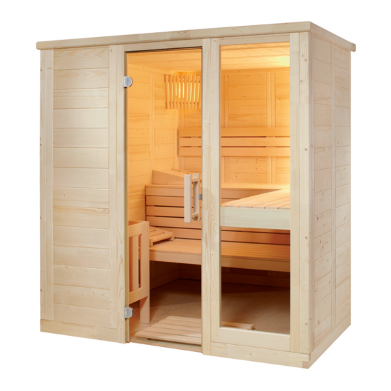
- Page 1 Solid wood sauna Komfort Small 208 x 158 x 204 cm INSTRUCTIONS FOR INSTALLATION AND USE English KOMFORT-S Version 12/18 item no. 1-030-276...
-
Page 2: Table Of Contents
Table of Contents 1.1. Tools required 1.2. Maintenance and cleaning 1.3. Disposal 1.4. KOMFORT SMALL parts list 2. Cabin installation 2.1. Base frame installation 2.2. Wall element assembly 2.3. Ceiling installation 2.4. Ventilation slit installation 2.6. Installing accessories 2.7. Installing glass door 2.8. - Page 3 These assembly instructions can also be found in the downloads section of our website: www.sentiotec.com/downloads. Before you begin work, check the parts list to ensure that all the individual parts have been delivered.
-
Page 4: Tools Required
Instructions for installation and use p. 4/28 1.1. Tools required Hammer with a wooden head or a mallet Cordless screwdriver with bits for cross-head screws and Torx Roller tape measure Drill bits with a diameter of 3 mm, 10 mm, 20 - 30 mm (for sauna heater power cable) Spirit level 1.5 mm hexagonal socket wrench... -
Page 5: Maintenance And Cleaning
Instructions for installation and use p. 5/28 1.2. Maintenance and cleaning The sauna should be cleaned with a damp cloth. Only use warm water – no cleaning products. We recommend heating the cabin once a month if the sauna is not used for a long time. -
Page 6: Komfort Small Parts List
Instructions for installation and use p. 6/28 1.4. Name Dimensions No. of items Base frame 2 Base frame 66 x 9 x 4 cm 1 Base frame 204 x 9 x 4 cm 2 Base frame 156 x 9 x 4 cm Wall elements 6 A/A wall elements 193 x 48 x 4 cm... - Page 7 Instructions for installation and use p. 7/28 No. of Name Dimensions items 1 Benches 195 x 62 x 9 cm 1 Bench 195 x 53 x 9 cm 1 Backrests 190 x 26 x 4 cm 1 Bench screen 195 x 35 x 4 cm 1 Heater protection grille - lime wood 57 x 75 x 2 cm 1 Heater protection grille - lime wood...
-
Page 8: Cabin Installation
Instructions for installation and use p. 8/28 2. Cabin installation plans on Page 26 and Page 27. 2.1. Base frame installation 204 cm 66 cm 66 cm 3 mm drill bit, 4 screws 4 x 70 mm... -
Page 9: Wall Element Assembly
Instructions for installation and use p. 9/28 2.2. Wall element assembly The corner posts and wall elements are connected with tongue and groove and are screwed together. The door frame is connected to the wall elements using “Multiclips”. A always refers to the visible side. This is labelled on the top side of the wall elements. - Page 10 Instructions for installation and use p. 10/28 8 screws 6 x 120 mm per corner post Symbolphoto Symbolphoto...
- Page 11 Instructions for installation and use p. 11/28 Installing wall elements The electrical element has drill holes for laying cables. For the position Electrical element on right - Exhaust air on rear left. Electrical element on left - Exhaust air on rear left. Symbolphoto Symbolphoto 4 screws 6 x 100 mm...
- Page 12 Instructions for installation and use p. 12/28 Inserting the door frame Remove transport strip from Insert door frame the door frame Push the corner post from above down onto the wall elements. When doing this, ensure that the Multiclips are correctly aligned (see below). The door frame must Multiclip...
- Page 13 Instructions for installation and use p. 13/28 Screwing wall elements together Check the right angle before screwing the wall elements together. Observe the tip on page 4. Wandelemente 15 Stk. 4x70 3 mm drill bit, 15 screws 4 x 70 mm...
-
Page 14: Ceiling Installation
Instructions for installation and use p. 14/28 2.3. Ceiling installation Roof support slats 4 cm Dachauflageleisten 14 Stk. 4x70 3 mm drill bit, 14 screws 4 x 70 mm... - Page 15 Instructions for installation and use p. 15/28 Ceiling elements Ceiling elements Dachelemente Symbolphoto 12 Stk. 4x70 3 mm drill bit, 12 screws 4 x 70 mm...
-
Page 16: Ventilation Slit Installation
Instructions for installation and use p. 16/28 2.4. Ventilation slit installation 3 mm drill bit, 4 screws 3.5 x 40 mm 2.5. Bench support slats 3 mm drill bit, 3 screws 5 x 70 mm 2 screws 4 x 60 mm... - Page 17 Instructions for installation and use p. 17/28 3 mm drill bit, 3 screws 5 x 70 mm 2 screws 4 x 60 mm Bench screen 4 screws 4 x 60 mm...
- Page 18 Instructions for installation and use p. 18/28 Backrests 3 mm drill bit, 3 screws 3.5 x 40 mm approx. 25 cm...
-
Page 19: Installing Accessories
Instructions for installation and use p. 19/28 2.6. Installing accessories Sauna lamp Insert lamp (not included in the scope of delivery) 3 mm drill bit, 2 screws 4 screws 3.5 x 40 mm... - Page 20 Instructions for installation and use p. 20/28 Heater protection grille Before installing the heater protection grille, drill the outlet for the heater cable in the electrical element. 2 screws 3.5 x 40 mm 4 screws 3.5 x 40 mm...
-
Page 21: Installing Glass Door
Instructions for installation and use p. 21/28 2.7. Installing glass door The glass door can be hinged to the left or right. Silicone or paper insert for glass the glass door screws 4 x 30 mm... - Page 22 Instructions for installation and use p. 22/28 Door handle The door handles are screwed together from the inside. Insert silicone ring in the drill holes Symbolphoto...
- Page 23 Instructions for installation and use p. 23/28 Door magnet and sleeve plate...
-
Page 24: Installing Roof Trim
Instructions for installation and use p. 24/28 2.8. Installing roof trim Install the roof trim only after you have inserted the cable to the sauna heater and to the sauna control unit. The slat on the electrical element may possibly have to be cropped. 3 mm drill bit, 10 screws 3.5 x 40 mm... -
Page 25: Installing Ceiling Cover Slat
Instructions for installation and use p. 25/28 2.9. Installing ceiling cover slat Install the ceiling cover slat only after you have inserted the cable to the sauna heater and to the sauna control unit. The slat on the electrical element may possibly have to be cropped. 12 screws 3.5 x 40 mm... - Page 26 Instructions for installation and use p. 26/28 3.1.
- Page 27 Instructions for installation and use p. 27/28 3.2.
- Page 28 GmbH | Division of Harvia Group | Oberregauer Straße 48, A-4844 Regau Phone +43 (0) 7672/277 20-567 | Fax -801 | info@sentiotec.com | www.sentiotec.com...
Need help?
Do you have a question about the Komfort Small and is the answer not in the manual?
Questions and answers