Table of Contents
Advertisement
Available languages
Available languages
Quick Links
Advertisement
Table of Contents

Subscribe to Our Youtube Channel
Related Manuals for Sentiotec PHONIX-S


Summary of Contents for Sentiotec PHONIX-S
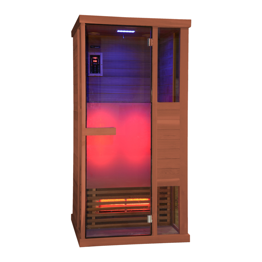
- Page 1 User´s manual Infrared Cabin PHÖNIX-S (1-030-313) 1/12 03/2021...
-
Page 2: Technical Data
PREFACE Thank you very much for purchasing our product. Please read this manual carefully before assembling and save it afterwards. Please write down the control box serial number of the cabin as this number will be required in case of repair or order of spare parts. ATTENTION Installation and repair should only be done by a qualified electrician! Check power supply rating and make sure the grounded outlet is correctly connected before installation. -
Page 3: Parts List
PARTS LIST Cabin Individual parts (variations possible) NAME Q’TY Floor panel (1020*998*65mm) Back panel (1927*940*43mm) Side panel 1 (1927*593*33mm) Side panel 2 (1927*593*33mm) Side glass (1896*344*6mm) Door jamb (1927*70*43mm) Front panel with glass (1927*344*48mm) Toppanel (1020*998*65mm) Bench support panel (898*468*33mm) Bench surface panel (900*500*33mm) Guardrail 1 (898*650*54mm) Guardrail 2 (650*260*54mm) - Page 4 Hardware parts (variations possible) Rubber strip Φ3*16 Φ4*45 Φ6*60 30*20*2 ASSEMBLE INSTRUCTIONS Assemble tips Please remove transport packaging and inspect that your infrared cabin has been delivered complete and intact before beginning assemble. A least 2 persons are required for assemble of the cabin Please check the countersink and hole diameter of the drill holes to avoid damaging the wood.
- Page 5 ASSEMBLE INSTRUCTIONS Assemble steps Note: back panel has ventilation slits must keep 5 cm away from the next wall Note: Note: about 20mm away connect calves from the bench panel heater cable 4-Φ4*45 5/12...
- Page 6 ASSEMBLE INSTRUCTIONS Assemble steps 6/12...
- Page 7 ASSEMBLE INSTRUCTIONS Assemble steps Note: connect all cables on the roof of the cabin 7/12...
-
Page 8: Circuit Diagram
CIRCUIT DIAGRAM 8/12... -
Page 9: Temperature Settings
OPERATING INTRUCTIONS Connect the power unit to wall outlet, the LED indicator will start to blink on the display. Now it is possible to switch on the infrared heaters, the light and the music function. 1) Startup Press to switch on the cabin and heaters start to work, the length of time is automatically set to 99 minutes and the air temperature inside the cabin will be displayed. -
Page 10: Use Instructions
SERVICE Use instructions Drink plenty of liquids before and after use of the infrared cabin. Dry yourself off completely. The optimal cabin temperature for a pleasant session lies between 35 and 40°C. After a heating period of an hour at the latest, the cabin should be switched off and a heating brake of at least 30 minutes should be taken. -
Page 11: Guarantee Card
SERVICE GUARANTEE CARD Fill in this form and make a picture of it and Email to: ______________________________________________ Date of purchase: _______________________________ Serial Number: _________________________________ Control unit label Reference number: ______________________________ Name: ________________________________________ Article state (unopened, just opened or used): ________ Please encircle on picture below which heater or which panel has a fault. - Page 12 GmbH | Division of Harvia Group | Wartenburger Straße 31, A-4840 Vöcklabruck T +43 (0) 7672/22 900-50| F -80 | info@sentiotec.com | www.sentiotec.com 12/12...
- Page 13 Benutzerhandbuch Infrarotkabine PHÖNIX-S (1-030-313) 1/12 03/2021...
- Page 14 EINLEITUNG Vielen Dank, dass Sie sich für unser Produkt entschieden haben. Bitte lesen Sie dieses Handbuch vor der Montage sorgfältig durch und bewahren Sie es auf. Schreiben Sie sich die Seriennummer der Kabine am Schaltkasten auf, da diese Nummer bei Reparaturen oder der Bestellung von Ersatzteilen erforderlich ist.
- Page 15 TEILELISTE Einzelteile der Kabine (Abweichungen möglich) NAME MENGE Bodenplatte (1020 x 998 x 65 mm) Rückwand (1927 x 940 x 43 mm) Seitenwand 1 (1927 x 593 x 33 mm) Seitenwand 2 (1927 x 593 x 33 mm) Seitenglas (1896 x 344 x 6 mm) Türpfosten (1927 x 70 x 43 mm) Vorderwand mit Glas (1927 x 344 x 48 mm) Deckenplatte (1020 x 998 x 65 mm)
- Page 16 Zubehörteile (Abweichungen möglich) Gummistreifen Φ 3 x 16 Φ 4 x 45 Φ 6 x 60 30 x 20 x 2 10 m 1 Stk. 33 Stk. 2 Stk. 1 Stk. MONTAGEANLEITUNG Hinweise zur Montage Entfernen Sie die Transportverpackung und prüfen Sie vor der Montage, ob die Infrarotkabine vollständig und in einwandfreiem Zustand geliefert wurde.
- Page 17 MONTAGEANLEITUNG Montageschritte Hinweis: Rückwand verfügt über Lüftungsschlitze; 5 cm Abstand zur Wand einhalten Hinweis: Hinweis: Schließen Sie das etwa 20 mm von der Kabel für das Waden- Bankplatte entfernt Heizelement an. 4-Φ4*45 5/12...
- Page 18 MONTAGEANLEITUNG Montageschritte 6/12...
- Page 19 MONTAGEANLEITUNG Montageschritte Steuerung Netzteil Gummi- streifen Griff Glastür Griff Hinweis: Schließen Sie alle Kabel auf dem Dach der Kabine an 7/12...
- Page 20 SCHALTPLAN Farbleuchte Bedienteil Steuerung Leistungsteil Waden Vorder- seite Rück- seite 8/12...
- Page 21 BEDIENUNGSANLEITUNG Verbinden Sie die Leistungseinheit mit der Wandsteckdose. Auf dem Display beginnt die LED-Anzeige zu blinken. Nun können die Infrarotheizelemente, die Leuchte und die Musikfunktion eingeschaltet werden. 1) Inbetriebnahme Drücken Sie auf , um die Kabine einzuschalten. Die Heizelemente beginnen zu heizen.
- Page 22 SERVICE Gebrauchsanleitung Trinken Sie viel Flüssigkeit vor und nach der Verwendung der Infrarotkabine. Trocknen Sie sich vollständig ab. Die optimale Kabinentemperatur für eine angenehme Sitzung liegt zwischen 35 und 40 °C. Spätestens nach einer Heizzeit von einer Stunde sollte die Kabine ausgeschaltet und eine Heizpause von mindestens 30 Minuten eingelegt werden.
- Page 23 SERVICE GARANTIEKARTE Füllen Sie dieses Formular aus, fotografieren/scannen Sie es, und senden Sie es per E-Mail an: ______________________________________________ Kaufdatum: ____________________________________ Steuergerätetikett Seriennummer: _________________________________ Referenznummer: _______________________________ Name: ________________________________________ Artikelzustand (ungeöffnet, vor Kurzem geöffnet oder gebraucht): ____________________________________ Kennzeichnen Sie in der folgenden Abbildung (mit einem Kreis), welches Heizelement oder welche Platte fehlerhaft ist.
- Page 24 GmbH | Division of Harvia Group | Wartenburger Straße 31, A-4840 Vöcklabruck T +43 (0) 7672/22 900-50| F -80 | info@sentiotec.com | www.sentiotec.com 12/12...
- Page 25 Manuel d’utilisateur Cabine infrarouge PHÖNIX-S (1-030-313) 1/12 03/2021...
-
Page 26: Caractéristiques Techniques
INTRODUCTION Merci d’avoir choisi notre produit. Veuillez lire attentivement ce manuel avant le montage et conservez-le. Notez le numéro de série de la cabine qui se trouve sur le boîtier de commande, car ce numéro est nécessaire pour toute réparation ou commande de pièces de rechange. -
Page 27: Liste Des Pièces
LISTE DES PIÈCES Pièces détachées de la cabine (divergences possibles) N° QUANTITÉ Plaque de sol (1020 x 998 x 65 mm) Paroi arrière (1927 x 940 x 43 mm) Paroi latérale 1 (1927 x 593 x 33 mm) Paroi latérale 2 (1927 x 593 x 33 mm) Verre latéral (1896 x 344 x 6 mm) Montant de porte (1927 x 70 x 43 mm) Paroi avant avec verre (1927 x 344 x 48 mm) -
Page 28: Instructions De Montage
Accessoires (divergences possibles) Bande en Φ 3 x 16 Φ 4 x 45 Φ 6 x 60 30 x 20 x 2 caoutchouc 10 m INSTRUCTIONS DE MONTAGE Remarques sur le montage Retirez l’emballage de transport et vérifiez, avant le montage, que la cabine infrarouge est complète et en parfait état au moment de la livraison. - Page 29 INSTRUCTIONS DE MONTAGE Étapes de montage Remarque : la paroi arrière comporte des fentes d’aération ; laissez une distance de 5 cm par rapport au mur. Remarque : Remarque : raccordez le câble de écart d’environ l’élément chauffant 20 mm par rapport pour les mollets.
- Page 30 INSTRUCTIONS DE MONTAGE Étapes de montage 6/12...
- Page 31 INSTRUCTIONS DE MONTAGE Étapes de montage externe uniquement Bloc d’alimentation Bande caout- Poignée chouc Porte en verre Poignée Remarque : raccordez tous les câbles sur le toit de la cabine 7/12...
-
Page 32: Schéma De Câblage
SCHÉMA DE CÂBLAGE Lumière Tension colorée Puissance Courant nominal Niveau de sécurité Modèle Panneau de commande externe uniquement Bloc de puissance Mollets Avant Arrière 8/12... - Page 33 MODE D’EMPLOI Branchez l’unité de puissance à la prise murale. L’affichage LED se met à clignoter sur l’écran. Il est maintenant possible d’activer les éléments chauffants infrarouges, la lumière et la fonction musicale. 1) Mise en service Appuyez sur pour mettre la cabine en marche. Les éléments chauffants commencent à...
-
Page 34: Instructions D'entretien
SERVICE Mode d’emploi Buvez beaucoup de liquide avant et après l’utilisation de la cabine infrarouge. Séchez-vous complètement. La température optimale de la cabine pour une séance agréable se situe entre 35 et 40 °C. Au plus tard après une heure de chauffe, la cabine doit être éteinte et le chauffage doit être interrompu pendant au moins 30 minutes. -
Page 35: Carte De Garantie
SERVICE CARTE DE GARANTIE Remplissez ce formulaire, photographiez/numérisez-le et envoyez-le par e-mail à : _____________________________________________ Date d’achat : __________________________________ Étiquette de l’appareil de commande Numéro de série : _______________________________ Numéro de référence : ___________________________ Nom : _________________________________________ État de l’article (non ouvert, tout juste ouvert ou utilisé) : Dans l’image ci-dessous, identifiez (par un cercle) l’élément chauffant ou le panneau défectueux. - Page 36 GmbH | Division of Harvia Group | Wartenburger Straße 31, A-4840 Vöcklabruck Tél. : +43 (0) 7672/22 900-50| F -80 | info@sentiotec.com | www.sentiotec.com 12/12...
- Page 37 Manuale d’uso Cabina a infrarossi PHÖNIX-S (1-030-313) 1/12 03/2021...
-
Page 38: Specifiche Tecniche
INTRODUZIONE Grazie per avere scelto il nostro prodotto. Si prega di leggere attentamente il presente manuale prima del montaggio e di conservarlo. Annotare il numero di serie della cabina sulla scatola di comando, poiché questo numero sarà necessario in caso di riparazioni o al momento di ordinare pezzi di ricambio. ATTENZIONE Il montaggio e la riparazione devono essere eseguiti solo da un elettricista qualificato! Controllare la potenza dell’alimentazione di corrente e assicurarsi che la presa a terra sia collegata... -
Page 39: Elenco Componenti
ELENCO COMPONENTI Singoli componenti della cabina (possibili scostamenti) NOME QUANTITÀ Piastra base (1020 x 998 x 65 mm) Pannello posteriore (1927 x 940 x 43 mm) Pannello laterale 1 (1927 x 593 x 33 mm) Pannello laterale 2 (1927 x 593 x 33 mm) Vetro laterale (1896 x 344 x 6 mm) Stipite della porta (1927 x 70 x 43 mm) Pannello anteriore con vetro (1927 x 344 x 48 mm) -
Page 40: Istruzioni Di Montaggio
Accessori (possibili scostamenti) Striscia in Φ 3 x 16 Φ 4 x 45 Φ 6 x 60 30 x 20 x 2 gomma 10 m 1 pz. 33 pz. 2 pz. 1 pz. ISTRUZIONI DI MONTAGGIO Indicazioni per il montaggio Rimuovere l’imballaggio di trasporto e controllare che la cabina a infrarossi sia stata consegnata completa e in perfette condizioni prima del montaggio. - Page 41 ISTRUZIONI DI MONTAGGIO Fasi di montaggio Indicazione: il pannello posteriore è dotato di fessure di ventilazione; mantenere una distanza di 5 cm dalla parete Indicazione: Indicazione: collegare il cavo per circa 20 mm dal l’elemento riscaldante pannello della panca della zona polpacci. 4-Φ4*45 5/12...
- Page 42 ISTRUZIONI DI MONTAGGIO Fasi di montaggio 6/12...
- Page 43 ISTRUZIONI DI MONTAGGIO Fasi di montaggio evaporatore Trasformatore Strisce - Maniglia gomma Porta in vetro Maniglia Indicazione: collegare tutti i cavi sul tetto della cabina 7/12...
-
Page 44: Schema Elettrico
SCHEMA ELETTRICO Lampada Tensione colorata Potenza Corrente nominale Livello di sicurezza Modello Unità di comando evaporatore Unità di potenza Zona polpacci Lato anteriore Lato posteriore 8/12... - Page 45 MANUALE Collegare l’unità di alimentazione alla presa di corrente. L’indicatore LED sul display inizia a lampeggiare. Ora gli elementi riscaldanti a infrarossi, la lampada e la funzione musicale possono essere attivati. 1) Messa in funzione Premere per accendere la cabina. Gli elementi riscaldanti inizieranno a riscaldarsi.
-
Page 46: Servizio Assistenza
SERVIZIO ASSISTENZA Istruzioni per l’uso Bere molti liquidi prima e dopo aver usato la cabina a infrarossi. Asciugarsi completamente. La temperatura ottimale della cabina per una piacevole sauna è tra 35 e 40 °C. Al più tardi dopo un’ora di riscaldamento, la cabina dovrebbe essere spenta e si dovrebbe fare una pausa di riscaldamento di almeno 30 minuti. -
Page 47: Scheda Di Garanzia
SERVIZIO ASSISTENZA SCHEDA DI GARANZIA Completare questo modulo, fotografarlo/scansionarlo e inviarlo via e-mail a: _____________________________________________ Data di acquisto: ________________________________ Etichetta dell’unità di comando Numero serie: __________________________________ Numero di riferimento: ___________________________ Nome: ________________________________________ Stato dell’articolo (non aperto, aperto di recente o usato): Nell’immagine seguente, contrassegnare (con un cerchio) quale elemento riscaldante o pannello è... - Page 48 GmbH | Division of Harvia Group | Wartenburger Straße 31, A-4840 Vöcklabruck T +43 (0) 7672/22 900-50| F -80 | info@sentiotec.com | www.sentiotec.com 12/12...
-
Page 49: Käyttäjän Käsikirja
Käyttäjän käsikirja Infrapunasauna PHÖNIX-S (1-030-313) 1/12 03/2021... -
Page 50: Tekniset Tiedot
JOHDANTO Hienoa, kun valitsit tuotteemme. Lue tämä käsikirja huolellisesti ennen asennusta ja säilytä se tulevaa käyttöä varten. Kirjoita muistiin saunan sarjanumero kytkentäkotelosta, koska voit tarvita tätä korjausten tai varaosien tilauksen yhteydessä. HUOMIO Ainoastaan sähköalan ammattilainen saa suorittaa asennuksen ja korjaustöitä! Varmista sähkösyötön teho sekä... - Page 51 OSALUETTELO Saunan yksittäisosat (mahdollisia poikkeuksia) NRO NIMI MÄÄRÄ Lattialevy (1020 x 998 x 65 mm) Takaseinä (1927 x 940 x 43 mm) Sivuseinä 1 (1927 x 593 x 33 mm) Sivuseinä 2 (1927 x 593 x 33 mm) Sivulasi (1896 x 344 x 6 mm) Ovilista (1927 x 70 x 43 mm) Etuseinä...
- Page 52 Lisävarusteet (mahdollisia poikkeuksia) Kumilista Φ 3 x 16 Φ 4 x 45 Φ 6 x 60 30 x 20 x 2 10 m 1 kpl 33 kpl 2 kpl 1 kpl ASENNUSOHJE Ohjeita asennukseen Poista kuljetuspakkaus ja tarkasta ennen asennusta, että infrapunasauna toimitettiin täydellisenä ja moitteettomassa kunnossa.
- Page 53 ASENNUSOHJE Asennusvaiheet Huomautus: Takaseinässä on tuuletusaukkoja; pidä 5 cm:n etäisyys seinään Huomautus: Huomautus: noin 20 mm Liitä pohjelämmitys laudelevystä poispäin vastuksen kaapeli. 4-Φ4*45 5/12...
- Page 54 ASENNUSOHJE Asennusvaiheet 6/12...
- Page 55 ASENNUSOHJE Asennusvaiheet Tehoyksikkö Virtalähde Kumilista Kahva Lasiovi Kahva Huomautus: Liitä kaikki kaapelit saunan kattoon 7/12...
- Page 56 Kytkentäkaavio Värivalo Ohjauspaneeli Tehoyksikkö Pohkeet Etuosa Takaosa 8/12...
- Page 57 KÄYTTÖOHJE Liitä tehoyksikkö seinäpistorasiaan. Näytön LED-valo alkaa vilkkua. Nyt voit käynnistää infrapunalämmitysvastukset, valon ja musiikkitoiminnon. 1) Käyttöönotto Kytke sauna päälle painamalla painiketta . Lämmitysvastukset aloittavat lämmityksen. Kesto säädetään automaattisesti 99 minuuttiin ja saunan ilmalämpötila tulee näkyviin. Kytke lämmitysvastukset pois painamalla painiketta uudelleen.
- Page 58 HUOLTO Käyttöohje Juo paljon nestettä, ennen kuin menet saunaan sekä sen jälkeen. Kuivaa itsesi huolellisesti. Saunan optimaalinen lämpötila mukavaa oleskelua varten on 35 ja 40 °C:een välissä. Sauna tulee kytkeä pois viimeistään tunnin lämmitysajan jälkeen ja pitää vähintään 30 minuutin lämmitystauko. Suosittelemme, että...
- Page 59 HUOLTO TAKUUKORTTI Täytä tämä lomake, valokuvaa tai skannaa se ja lähetä sähköpostilla osoitteeseen: ______________________________________________ Ostopäivämäärä: ________________________________ Ohjauskeskuksen etiketti Sarjanumero: ___________________________________ Viitenumero: ___________________________________ Nimi: _________________________________________ Tuotteen tila (avaamaton, hiljattain avattu tai käytetty): ___________________________________ Merkitse seuraavaan kuvaan (ympyrällä) mikä lämmitysvastus tai mikä levy on kyseessä. Lisää...
- Page 60 GmbH | Division of Harvia Group | Wartenburger Straße 31, A-4840 Vöcklabruck T +43 (0) 7672/22 900-50| F -80 | info@sentiotec.com | www.sentiotec.com 12/12...
Need help?
Do you have a question about the PHONIX-S and is the answer not in the manual?
Questions and answers