Sentiotec COUNTRY Assembly Instructions And User's Manual
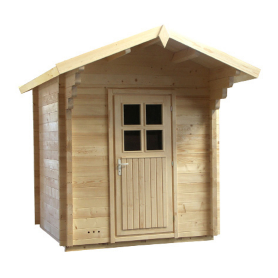
Garden sauna 319x264x290 cm
Hide thumbs
Also See for COUNTRY:
- Assembly instructions manual (44 pages) ,
- Assembly instructions manual (60 pages)
Advertisement
Quick Links
Advertisement

Related Manuals for Sentiotec COUNTRY


Summary of Contents for Sentiotec COUNTRY
- Page 1 Assembly Instruction COUNTRY Garden sauna 319 x 264 x 290 cm Version 10/17...
- Page 2 Assembly instructions Garden sauna COUNTRY Exterior dimension: 319 x 264 x 290 cm Interior dimension: 200 x 200 x 210 cm Wall thickness: 70 mm Dear customer, Before you begin with the work, check that all the individual parts have been delivered against the parts list.
- Page 3 COUNTRY parts list Front face with doors 3 floor frames 206 x 8 x 4 cm 2 floor frames 206 x 12 x 4 cm 1 block plank 230 x 6.5 x 7 cm with recess for 22 floor boards 199.5 x 9.5 x 1.9 cm door frame and 4 recesses for threaded rods 4 skirting boards 200 x 2.5 x 2.5 cm...
- Page 4 (municipal office, magistrate). You may need this as permission is required above a certain room volume. This depends on where you live exactly and is therefore handled differently from country to country. Check...
- Page 5 However, the two options below have proven to be the best in practice: • Foundation slab (base plate) • Strip foundation For both types, a foundation that is absolutely flat and load-bearing must be ensured. Only then can the assembly of the individual modules be ensured without any difficulties and with a precise fit.
- Page 6 Assembly instructions Strip foundation Depending on the structural requirements and local conditions, strip foundations can be laid in different ways. There are two types of strip foundations: • strip foundation - not reinforced • strip foundation - reinforced To make a frost-proof strip foundation, you must dig at least 80 cm deep into the ground. The supporting walls of the garden sauna are then laid on the foundation strips.
- Page 7 Note: The foundations must be absolutely flat to ensure the load-bearing capacity of the sauna. If the foundation slab is larger than the floor space of the garden sauna, rainwater can start to collect around the sauna This means that the wooden wall elements would be constantly standing on wet ground.
- Page 8 Assembly instructions Base frame for outer sauna Screws 4 x 60 mm Fig. 1.1 Screws 5 x 100 mm Fig. 1.2 1 block plank 230 x 6.5 x 7 cm with recesses for threaded rods Fig. 1.3 1 block plank 230 x 6.5 x 7 cm with recesses for threaded rods and doors...
- Page 9 1 block plank 230 x 14.6 x 7 cm with ventilation recess Fig. 1.4 1 block plank 69 x 14.6 x 7 cm with drill holes for supply air Fig. 1.5...
- Page 10 Assembly instructions Fig. 1.6 Threaded rods 8 mm Fig. 1.7 Fig. 1.8...
- Page 11 Screw joints at top – cut off the remaining threaded rod above the nut Fig. 1.9 Fig. 1.10 Screw joints at bottom Fig. 1.11...
- Page 12 Assembly instructions Fig.1.12 Ventilation shutter 4 screws 3 x 40 mm Fig. 1.13...
- Page 13 Fig.1.21 Fig. 1.14 Floor - screws 3.5 x 50 mm Screws 5 x 100 mm Fig. 1.15 Skirting board - screws 3.2 x 40 mm...
- Page 14 Assembly instructions Screws 4 x 70 mm Measure from floor to the bottom edge of the roof support slat 206 cm. 206 cm Fig. 1.16 Fig. 1.17...
- Page 15 Fig. 1.18 Screw the roof elements from above with the support slats Screws x 80 mm Fig. 1.19...
- Page 16 Assembly instructions Screws 5 x 70 mm 87 cm 41 cm Fig. 1.20 Fig. 1.21...
- Page 17 Screws 3.5 x 50 mm Bench screen - view from rear Fig. 1.22 Bench screen Fig. 1.23...
- Page 18 Assembly instructions Screws 3.5 x 50 mm 25 cm Fig. 1.24 4 screws 3 x 40 mm Fig. 1.25 Fig. 1.26 Fig. 1.27...
- Page 19 First put the mounting slats of the door and the screws in the cabin. Then place the door element in the doorway, take the top slat (1), place it so that left and right is the same and screw the slat to the door. Next, screw on the side mounting slats.
- Page 20 Assembly instructions Screws 3 x 40 mm Fig. 1.35 Fig. 1.36...
- Page 21 Screws 3.5 x 50 mm 2 cm Fig. 1.28 Fig. 1.29 Wind board, side, screws 3.5 x 50 mm Fig. 1.30 Screws 3.5 x 50 mm Fig. 1.31...
- Page 22 Assembly instructions Screws 3.5 x 50 mm Fig. 1.31 Weather boards, side Fig. 1.32...
- Page 23 Fig. 1.37 Place the two rows of roofing felt for each wall side with overhang and fasten it with roofing felt nails. Finally, place another row of roofing felt over the weather board and fasten it again with roofing felt nails. Fig. 1.38...
- Page 24 COUNTRY FLOOR PLAN 319 x 264 x 290 cm...
- Page 25 GmbH | Division of Harvia Group | Oberregauer Straße 48, A-4844 Regau T +43 (0) 7672/277 20-567 | F -801 | info@sentiotec.com | www.sentiotec.com...
Need help?
Do you have a question about the COUNTRY and is the answer not in the manual?
Questions and answers